|
| Multiple board installation 49 | ||
|
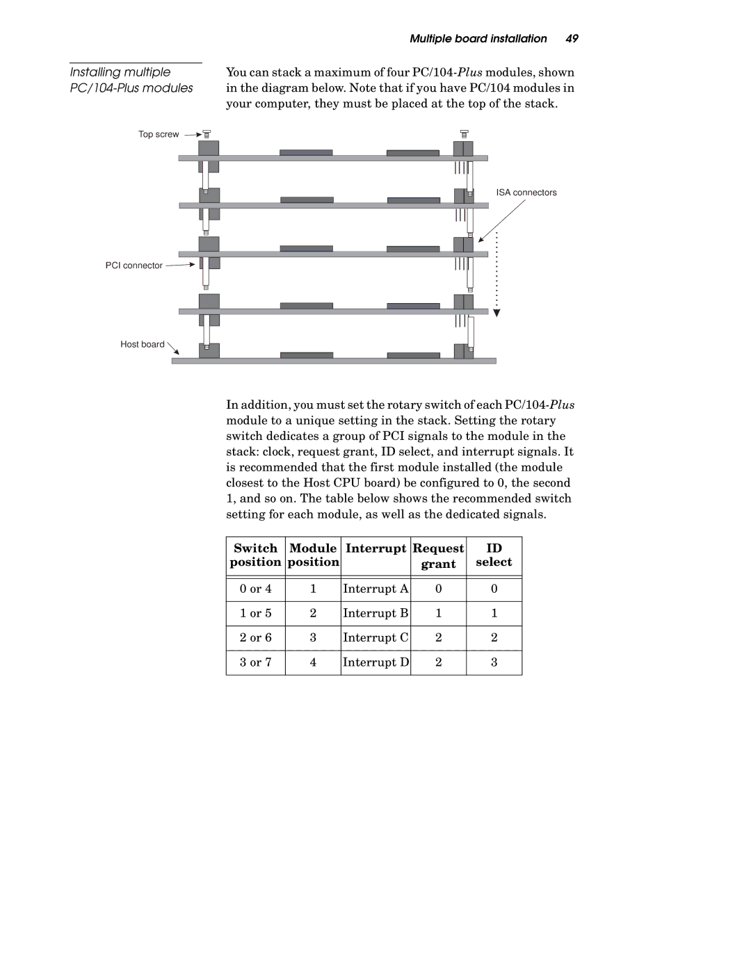
| You can stack a maximum of four | ||
Installing multiple |
| |||
|
| in the diagram below. Note that if you have PC/104 modules in | ||
|
| your computer, they must be placed at the top of the stack. | ||
Top screw |
|
|
|
|
|
|
|
|
|
|
|
|
|
|
|
|
|
|
|
|
|
|
|
|
|
|
|
|
|
ISA connectors
PCI connector
Host board |
In addition, you must set the rotary switch of each
Switch | Module | Interrupt | Request | ID |
position | position |
| grant | select |
|
|
|
|
|
|
|
|
|
|
0 or 4 | 1 | Interrupt A | 0 | 0 |
|
|
|
|
|
1 or 5 | 2 | Interrupt B | 1 | 1 |
|
|
|
|
|
2 or 6 | 3 | Interrupt C | 2 | 2 |
|
|
|
|
|
3 or 7 | 4 | Interrupt D | 2 | 3 |
|
|
|
|
|
