90 Appendix B: Technical information Matrox
Pin | Signal | Pin | Signal |
|
|
|
|
27 | DATA[22] | 61 | DATA[23] |
|
|
|
|
28 | DGND | 62 | DATA[24] |
|
|
|
|
29 | DATA[25] | 63 | DGND |
|
|
|
|
30 | DATA[26] | 64 | DATA[27] |
|
|
|
|
31 | DGND | 65 | DATA[28] |
|
|
|
|
32 | DATA[29] | 66 | DGND |
|
|
|
|
33 | DATA[30] | 67 | DATA[31] |
|
|
|
|
34 | DGND | 68 | SBN |
|
|
|
|
*N/C = Not connected. This means that the pin might be defined as part of the VMChannel interface standard but it is not used on the Matrox
2
1
4
3
2 1
BNC connector
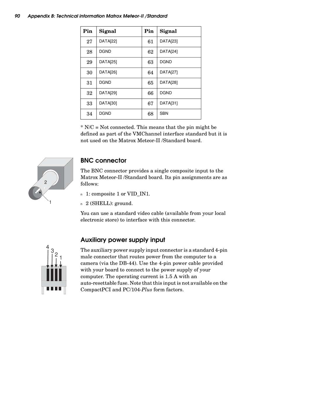
The BNC connector provides a single composite input to the Matrox
■1: composite 1 or VID_IN1.
■2 (SHELL): ground.
You can use a standard video cable (available from your local electronic store) to interface with this connector.
Auxiliary power supply input
The auxiliary power supply input connector is a standard
