Board input and output connectors 91
The pinout of the auxiliary power supply input connector is as follows:
Pin | Description |
|
|
1 | +12 V |
|
|
2 | Ground |
|
|
3 | Ground |
|
|
4 | +5 V |
|
|
For customers building their own cable, the part number of the camera supply connector is as follows:
■ Manufacturer: VEN
■Connector:
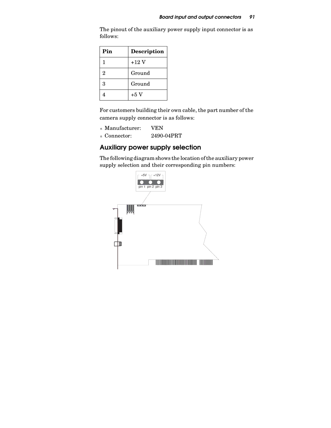
Auxiliary power supply selection
The following diagram shows the location of the auxiliary power supply selection and their corresponding pin numbers:
+5V +12V
pin 2 pin 3