Connecting external devices 35
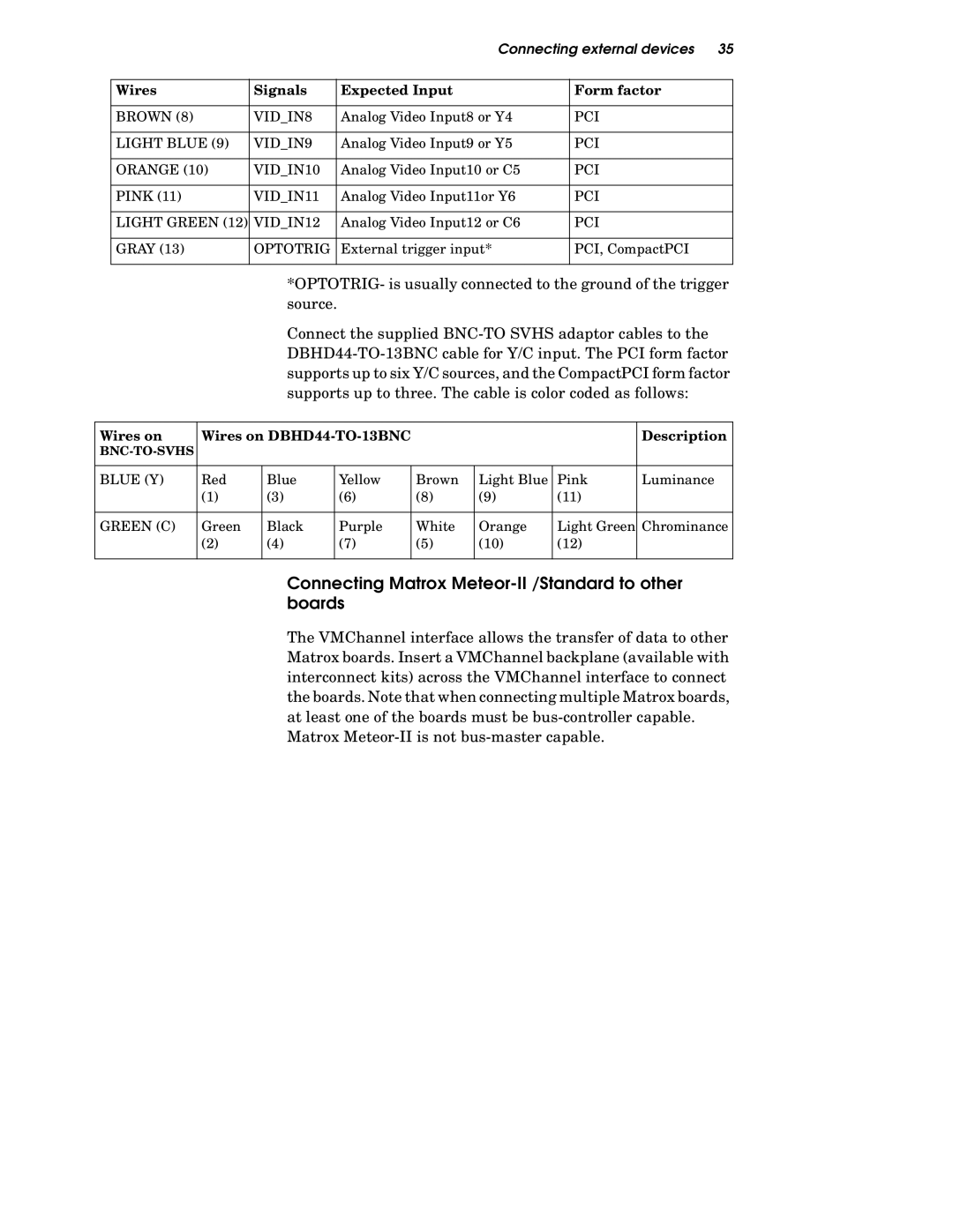
Wires | Signals | Expected Input | Form factor |
|
|
|
|
BROWN (8) | VID_IN8 | Analog Video Input8 or Y4 | PCI |
|
|
|
|
LIGHT BLUE (9) | VID_IN9 | Analog Video Input9 or Y5 | PCI |
|
|
|
|
ORANGE (10) | VID_IN10 | Analog Video Input10 or C5 | PCI |
|
|
|
|
PINK (11) | VID_IN11 | Analog Video Input11or Y6 | PCI |
|
|
|
|
LIGHT GREEN (12) | VID_IN12 | Analog Video Input12 or C6 | PCI |
|
|
|
|
GRAY (13) | OPTOTRIG | External trigger input* | PCI, CompactPCI |
|
|
|
|
*OPTOTRIG- is usually connected to the ground of the trigger source.
Connect the supplied
Wires on | Wires on |
|
|
| Description | ||
|
|
|
|
|
|
| |
|
|
|
|
|
|
|
|
BLUE (Y) | Red | Blue | Yellow | Brown | Light Blue | Pink | Luminance |
| (1) | (3) | (6) | (8) | (9) | (11) |
|
|
|
|
|
|
|
|
|
GREEN (C) | Green | Black | Purple | White | Orange | Light Green | Chrominance |
| (2) | (4) | (7) | (5) | (10) | (12) |
|
|
|
|
|
|
|
|
|
Connecting Matrox Meteor-II /Standard to other boards
The VMChannel interface allows the transfer of data to other Matrox boards. Insert a VMChannel backplane (available with interconnect kits) across the VMChannel interface to connect the boards. Note that when connecting multiple Matrox boards, at least one of the boards must be
Matrox