34 Chapter 2: Hardware installation
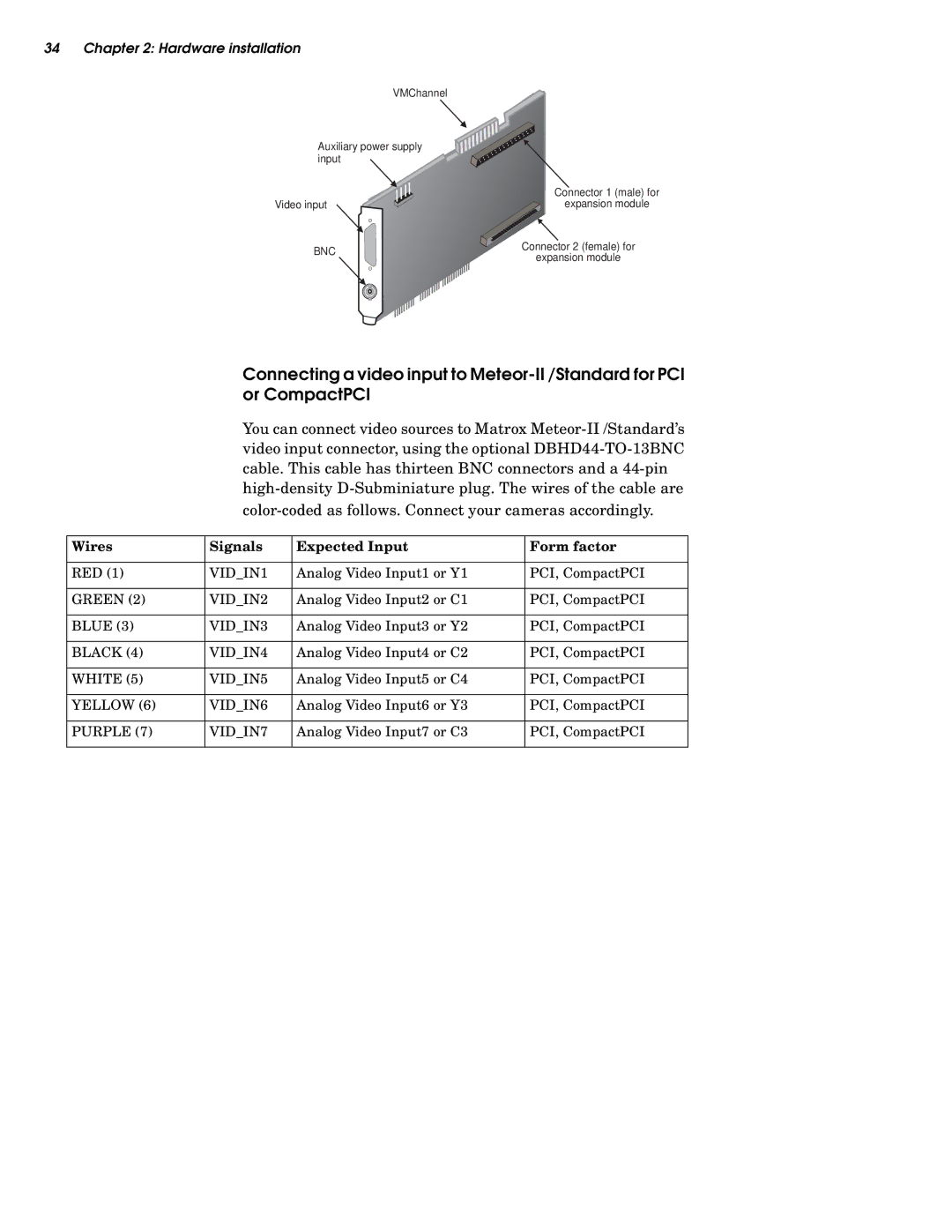
VMChannel |
| |
Auxiliary power supply |
| |
input |
| |
| Connector 1 (male) for | |
Video input | expansion module | |
BNC | Connector 2 (female) for | |
expansion module | ||
|
Connecting a video input to
You can connect video sources to Matrox
Wires | Signals | Expected Input | Form factor |
|
|
|
|
RED (1) | VID_IN1 | Analog Video Input1 or Y1 | PCI, CompactPCI |
|
|
|
|
GREEN (2) | VID_IN2 | Analog Video Input2 or C1 | PCI, CompactPCI |
|
|
|
|
BLUE (3) | VID_IN3 | Analog Video Input3 or Y2 | PCI, CompactPCI |
|
|
|
|
BLACK (4) | VID_IN4 | Analog Video Input4 or C2 | PCI, CompactPCI |
|
|
|
|
WHITE (5) | VID_IN5 | Analog Video Input5 or C4 | PCI, CompactPCI |
|
|
|
|
YELLOW (6) | VID_IN6 | Analog Video Input6 or Y3 | PCI, CompactPCI |
|
|
|
|
PURPLE (7) | VID_IN7 | Analog Video Input7 or C3 | PCI, CompactPCI |
|
|
|
|