38Chapter 2: Hardware installation
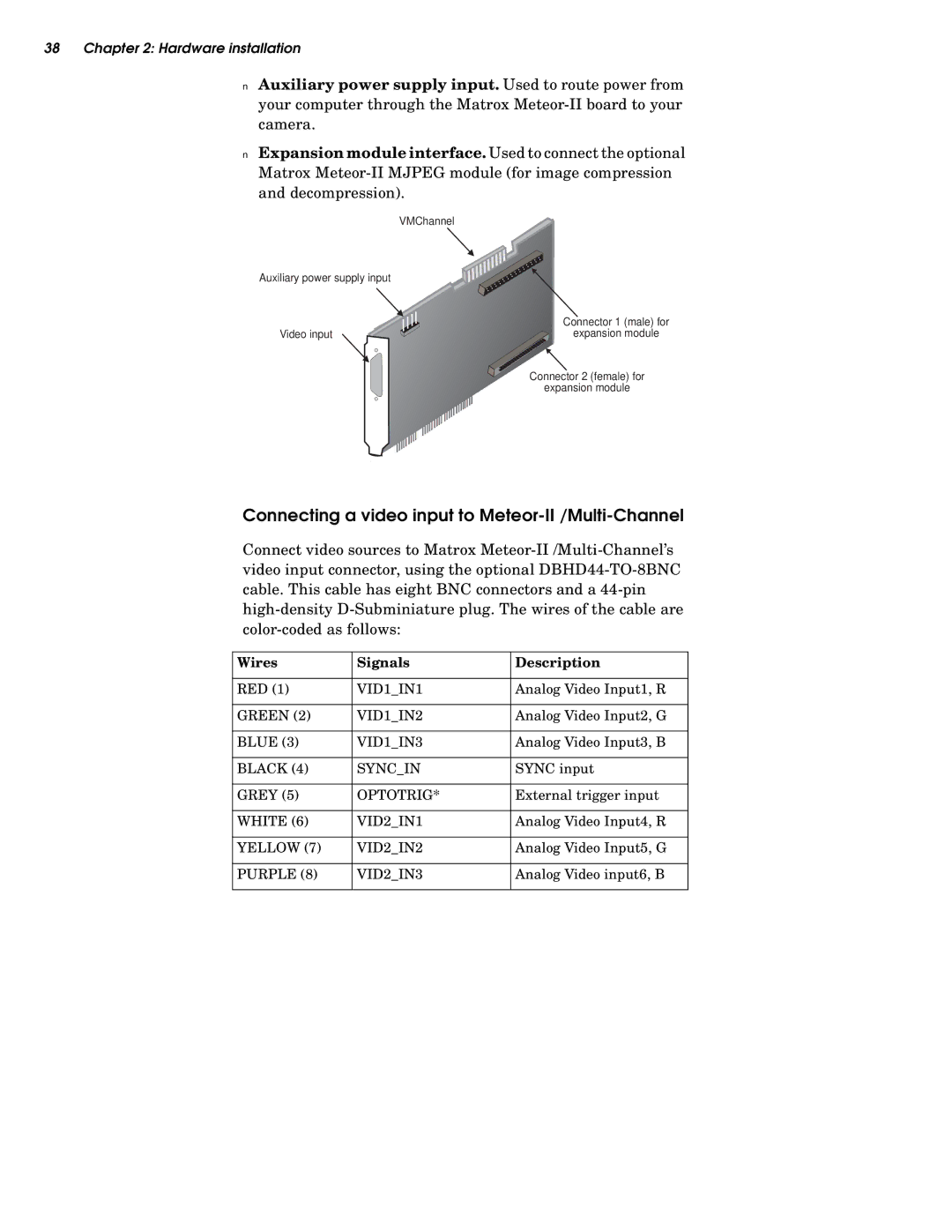
■Auxiliary power supply input. Used to route power from your computer through the Matrox
■Expansion module interface. Used to connect the optional Matrox
| VMChannel |
Auxiliary power supply input |
|
| Connector 1 (male) for |
Video input | expansion module |
| Connector 2 (female) for |
| expansion module |
Connecting a video input to Meteor-II /Multi-Channel
Connect video sources to Matrox
Wires | Signals | Description |
|
|
|
RED (1) | VID1_IN1 | Analog Video Input1, R |
|
|
|
GREEN (2) | VID1_IN2 | Analog Video Input2, G |
|
|
|
BLUE (3) | VID1_IN3 | Analog Video Input3, B |
|
|
|
BLACK (4) | SYNC_IN | SYNC input |
|
|
|
GREY (5) | OPTOTRIG* | External trigger input |
|
|
|
WHITE (6) | VID2_IN1 | Analog Video Input4, R |
|
|
|
YELLOW (7) | VID2_IN2 | Analog Video Input5, G |
|
|
|
PURPLE (8) | VID2_IN3 | Analog Video input6, B |
|
|
|