*If any of the items is damaged or missing, please contact your retailer immediately.
1.4 Front panel LED indicators
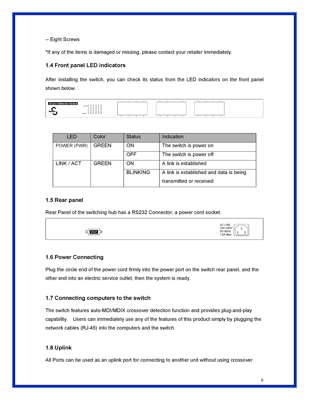
After installing the switch, you can check its status from the LED indicators on the front panel shown below.
LED | Color | Status | Indication |
|
|
|
|
POWER (PWR) | GREEN | ON | The switch is power on |
|
|
|
|
|
| OFF | The switch is power off |
|
|
|
|
LINK / ACT | GREEN | ON | A link is established |
|
|
|
|
|
| BLINKING | A link is established and data is being |
|
|
| transmitted or received |
|
|
|
|
1.5 Rear panel
Rear Panel of the switching hub has a RS232 Connector, a power cord socket.
1.6 Power Connecting
Plug the circle end of the power cord firmly into the power port on the switch rear panel, and the other end into an electric service outlet, then the system is ready.
1.7 Connecting computers to the switch
The switch features
1.8 Uplink
All Ports can be used as an uplink port for connecting to another unit without using crossover
6