60 Chapter 5: Matrox
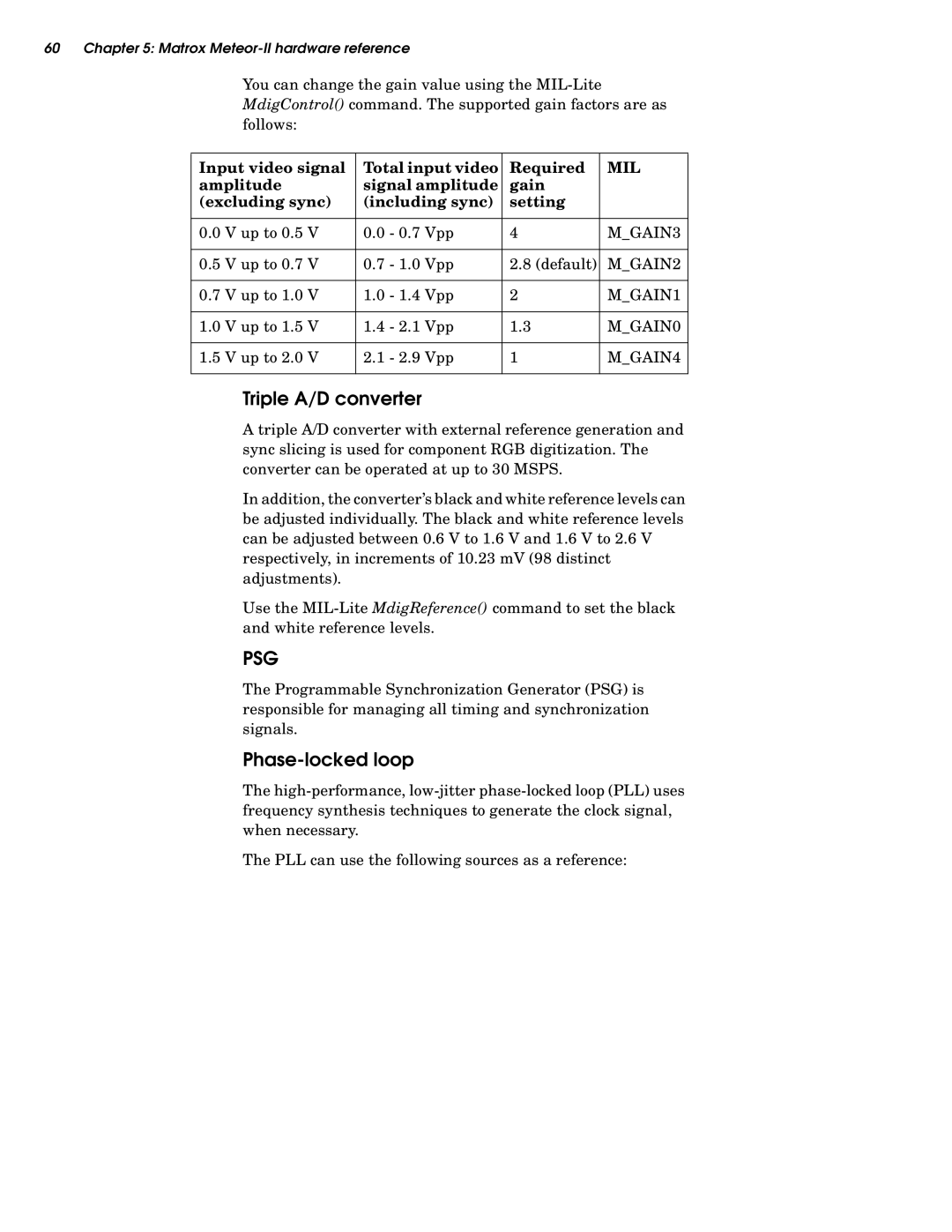
You can change the gain value using the
Input video signal | Total input video | Required | MIL |
amplitude | signal amplitude | gain |
|
(excluding sync) | (including sync) | setting |
|
|
|
|
|
0.0 V up to 0.5 V | 0.0 - 0.7 Vpp | 4 | M_GAIN3 |
|
|
|
|
0.5 V up to 0.7 V | 0.7 - 1.0 Vpp | 2.8 (default) | M_GAIN2 |
|
|
|
|
0.7 V up to 1.0 V | 1.0 - 1.4 Vpp | 2 | M_GAIN1 |
|
|
|
|
1.0 V up to 1.5 V | 1.4 - 2.1 Vpp | 1.3 | M_GAIN0 |
|
|
|
|
1.5 V up to 2.0 V | 2.1 - 2.9 Vpp | 1 | M_GAIN4 |
|
|
|
|
Triple A/D converter
A triple A/D converter with external reference generation and sync slicing is used for component RGB digitization. The converter can be operated at up to 30 MSPS.
In addition, the converter’s black and white reference levels can be adjusted individually. The black and white reference levels can be adjusted between 0.6 V to 1.6 V and 1.6 V to 2.6 V respectively, in increments of 10.23 mV (98 distinct adjustments).
Use the
PSG
The Programmable Synchronization Generator (PSG) is responsible for managing all timing and synchronization signals.
Phase-locked loop
The
The PLL can use the following sources as a reference:
