Manuals
/
ADTRAN
/
Computer Equipment
/
Network Router
ADTRAN
1700600L2, 1700611G2, 1700601G2
manual
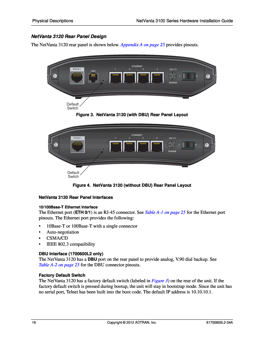
NetVanta 3120 Rear Panel Design
Models:
1700601G2
1700600L2
1700611G2
1
16
26
26
Download
26 pages
19.36 Kb
13
14
15
16
17
18
19
20
Install
Safety
Supplying Power to the Unit
Service and Warranty
Page 16
Image 16
Page 15
Page 17
Page 16
Image 16
Page 15
Page 17
Contents
NetVanta 3100 Series Fixed Port Routers Hardware Installation Guide
To the Holder of the Manual
Trademarks
Software Licensing Agreement
Conventions
Notes provide additional useful information
Save These Important Safety Instructions
Safety Instructions
These units contain no user-serviceable parts
FCC-Required Information
Service and Warranty
FCC Radio Frequency Interference Statement
Industry Canada Compliance Information
Canadian Emissions Requirements
Appendix A. Connector Pin Definitions
Table of Contents
Introduction Physical Descriptions
Table of Contents
List of Figures
List of Figures
List of Tables
Table A-1
Table A-2
Table A-3
List of Tables
Mounting Options on page Supplying Power to the Unit on page
Physical Descriptions on page Unit Installation on page
1. INTRODUCTION
NetVanta 3120 Features and Specifications
2. PHYSICAL DESCRIPTIONS NetVanta
NetVanta 3120 Shipping Contents
NetVanta 3120 Front Panel Design
NetVanta 3120 Rear Panel Design
NetVanta 3130 Features and Specifications
NetVanta
NetVanta 3130 Front Panel Design
NetVanta 3130 Shipping Contents
Figure 5. NetVanta 3130 with DBU Front Panel Layout
NetVanta 3130 Rear Panel Design
DBU Interface 1700610L2 only
NetVanta 3100 Series Front Panel LEDs
Table 1 describes the front panel LEDs
Table 1. NetVanta 3100 Series Front Panel LEDs
Color
3. UNIT INSTALLATION
Tools Required
Mounting Options
Tabletop Mounting the NetVanta 3100 Series
Proceed to the steps given in Supplying Power to the Unit on page
Instructions for Wall Mounting NetVanta 3100 Series
Step
Action
Supplying Power to the Unit
APPENDIX A. CONNECTOR PIN DEFINITIONS
Base Unit Pinouts
Table A-2. DBU Connector Pinouts
Table A-3. ADSL Connector Pinouts
Appendix A. Connector Pin Definitions
Top
Page
Image
Contents