Wiring
The ADTRAN IDSL
CAUTION
On
Span Power Applications |
| |
• | Single Mount Housing | P/N 1212007L1 |
• | Dual Mount Housing | P/N 1212008L1 |
For
Local Power Applications |
|
• Single Mount Housing | P/N 1212007L2 |
For
Table 3 shows the Compliance Codes for the IDSL
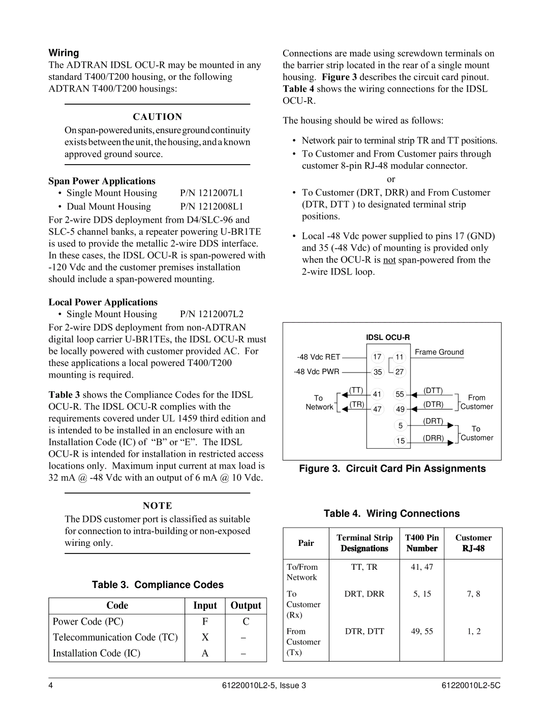
Connections are made using screwdown terminals on the barrier strip located in the rear of a single mount housing. Figure 3 describes the circuit card pinout.
Table 4 shows the wiring connections for the IDSL
The housing should be wired as follows:
•Network pair to terminal strip TR and TT positions.
•To Customer and From Customer pairs through customer
or
•To Customer (DRT, DRR) and From Customer (DTR, DTT ) to designated terminal strip positions.
•Local
|
| IDSL |
|
| |
| 17 | 11 | Frame Ground | ||
|
|
| |||
| 35 | 27 |
|
| |
To | (TT) | 41 | 55 | (DTT) | From |
|
| ||||
(TR) |
|
| (DTR) | ||
Network | 47 | 49 | Customer | ||
|
|
|
| ||
|
|
| 5 | (DRT) | To |
|
|
|
| ||
|
|
|
|
| |
|
|
| 15 | (DRR) | Customer |
|
|
|
|
| |
Figure 3. Circuit Card Pin Assignments
NOTE
The DDS customer port is classified as suitable for connection to
Table 3. Compliance Codes
Code | Input | Output |
|
|
|
Power Code (PC) | F | C |
Telecommunication Code (TC) | X | – |
Installation Code (IC) | A | – |
|
|
|
Table 4. Wiring Connections
Pair | Terminal Strip | T400 Pin | Customer | |
Designations | Number | |||
| ||||
|
|
|
| |
To/From | TT, TR | 41, 47 |
| |
Network |
|
|
| |
To | DRT, DRR | 5, 15 | 7, 8 | |
Customer |
|
|
| |
(Rx) |
|
|
| |
From | DTR, DTT | 49, 55 | 1, 2 | |
Customer |
|
|
| |
(Tx) |
|
|
| |
|
|
|
|
4 |