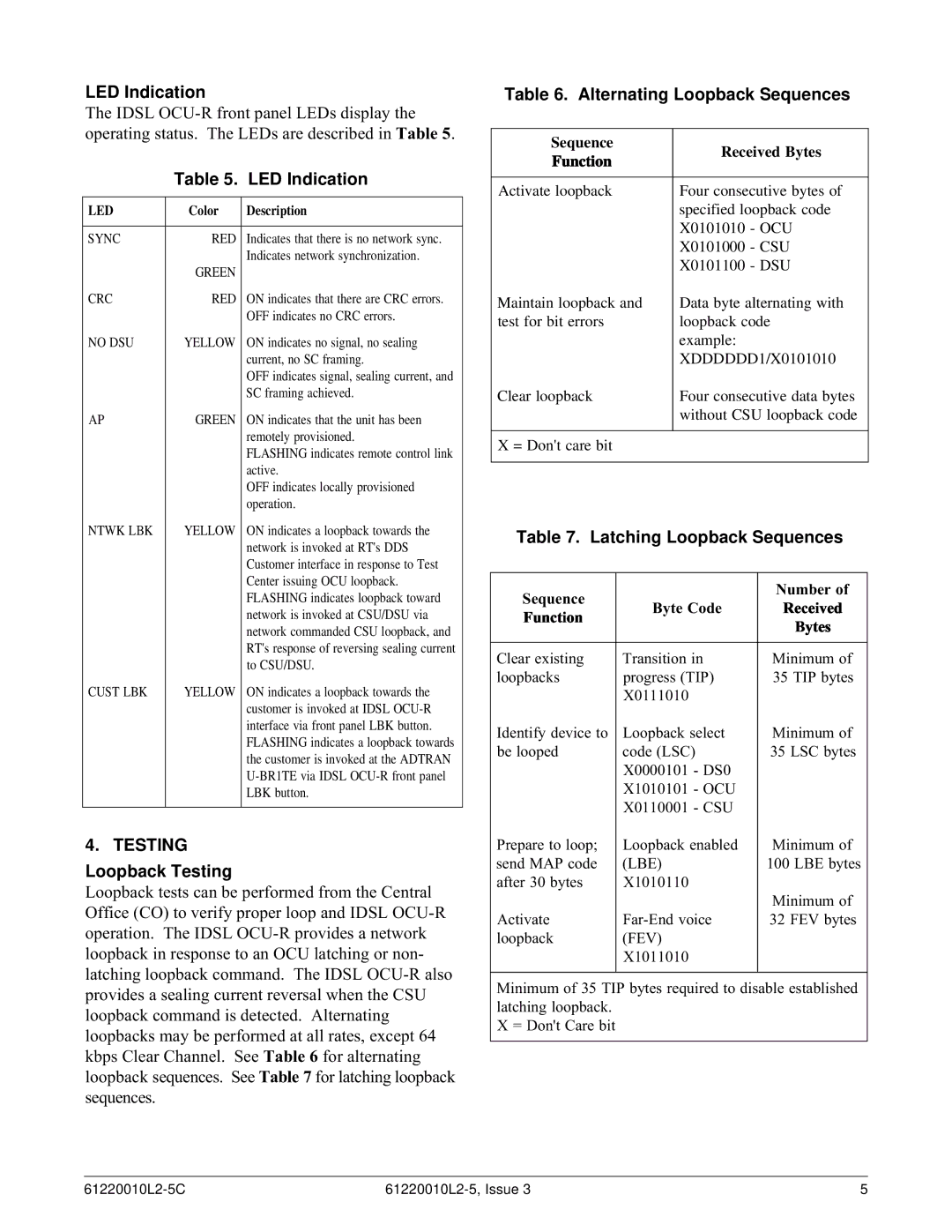
LED Indication
The IDSL
| Table 5. | LED Indication |
|
|
|
LED | Color | Description |
|
|
|
SYNC | RED | Indicates that there is no network sync. |
|
| Indicates network synchronization. |
| GREEN |
|
CRC | RED | ON indicates that there are CRC errors. |
|
| OFF indicates no CRC errors. |
NO DSU | YELLOW | ON indicates no signal, no sealing |
|
| current, no SC framing. |
|
| OFF indicates signal, sealing current, and |
|
| SC framing achieved. |
AP | GREEN | ON indicates that the unit has been |
|
| remotely provisioned. |
|
| FLASHING indicates remote control link |
|
| active. |
|
| OFF indicates locally provisioned |
|
| operation. |
NTWK LBK | YELLOW | ON indicates a loopback towards the |
|
| network is invoked at RT's DDS |
|
| Customer interface in response to Test |
|
| Center issuing OCU loopback. |
|
| FLASHING indicates loopback toward |
|
| network is invoked at CSU/DSU via |
|
| network commanded CSU loopback, and |
|
| RT's response of reversing sealing current |
|
| to CSU/DSU. |
CUST LBK | YELLOW | ON indicates a loopback towards the |
|
| customer is invoked at IDSL |
|
| interface via front panel LBK button. |
|
| FLASHING indicates a loopback towards |
|
| the customer is invoked at the ADTRAN |
|
| |
|
| LBK button. |
|
|
|
4. TESTING
Loopback Testing
Loopback tests can be performed from the Central Office (CO) to verify proper loop and IDSL
Table 6. Alternating Loopback Sequences
Sequence | Received Bytes | |
Function | ||
| ||
|
| |
Activate loopback | Four consecutive bytes of | |
| specified loopback code | |
| X0101010 - OCU | |
| X0101000 - CSU | |
| X0101100 - DSU | |
Maintain loopback and | Data byte alternating with | |
test for bit errors | loopback code | |
| example: | |
| XDDDDDD1/X0101010 | |
Clear loopback | Four consecutive data bytes | |
| without CSU loopback code | |
|
| |
X = Don't care bit |
| |
|
|
Table 7. Latching Loopback Sequences
Sequence |
|
| Number of | |
Byte Code | Received | |||
Function | ||||
|
| Bytes | ||
|
|
| ||
|
|
| ||
Clear existing | Transition in | Minimum of | ||
loopbacks | progress (TIP) | 35 TIP bytes | ||
| X0111010 |
|
| |
Identify device to | Loopback select | Minimum of | ||
be looped | code (LSC) | 35 LSC bytes | ||
| X0000101 | - DS0 |
| |
| X1010101 | - OCU |
| |
| X0110001 | - CSU |
| |
Prepare to loop; | Loopback enabled | Minimum of | ||
send MAP code | (LBE) |
| 100 LBE bytes | |
after 30 bytes | X1010110 |
|
| |
|
|
| Minimum of | |
Activate | 32 FEV bytes | |||
loopback | (FEV) |
|
| |
| X1011010 |
|
| |
|
|
|
| |
Minimum of 35 TIP bytes required to disable established latching loopback.
X = Don't Care bit
5 |