ASC 9Eh
Local Loop
IDSL
Loopback
Pushbutton
Push once for
CPE Interface
Test
Set
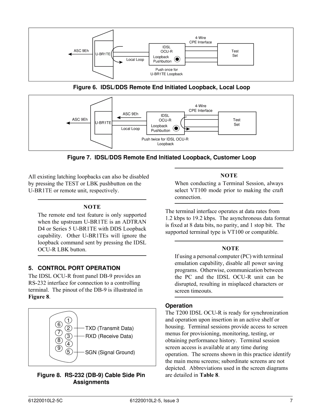
Figure 6. IDSL/DDS Remote End Initiated Loopback, Local Loop
ASC 9Eh
CPE Interface
| ASC 9Eh | IDSL | |
|
|
| |
|
|
| |
|
|
| Loopback |
| Local Loop | ||
| Pushbutton | ||
|
|
| |
|
|
|
|
Push twice for IDSL
Loopback
Test
Set
Figure 7. IDSL/DDS Remote End Initiated Loopback, Customer Loop
All existing latching loopbacks can also be disabled by pressing the TEST or LBK pushbutton on the
NOTE
The remote end test feature is only supported when the upstream
5. CONTROL PORT OPERATION
The IDSL
Figure 8.
1
6
2 TXD (Transmit Data)
7
3 RXD (Receive Data)
8
4
9
5 | SGN (Signal Ground) |
Figure 8. RS-232 (DB-9) Cable Side Pin
Assignments
NOTE
When conducting a Terminal Session, always select VT100 mode prior to making the craft connection.
The terminal interface operates at data rates from
1.2kbps to 19.2 kbps. The asynchronous data format is fixed at 8 data bits, no parity, and 1 stop bit. The supported terminal type is VT100 or compatible.
NOTE
If using a personal computer (PC) with terminal emulation capability, disable all power saving programs. Otherwise, communication between the PC and the IDSL
Operation
The T200 IDSL
7 |
