1st Ed January
Mini-ITX AIMB-250 Series
Copyright Notice
FCC Statement
Trademark Acknowledgement
AIMB-250 Series
Life Support Policy
Disclaimer
Message to the Customer
User’s Manual
Advantech Corp
Technical Support
Product Warranty
Contents
Bios Setup
Memory Size has Changed Since Last Boot
Keyboard Error or no Keyboard Present
System HALTED, CTRL-ALT-DEL to Reboot
Offending Address not Found
Hard Disks fail → Unable to recalibrate fixed disk
Packing List
Safety Precautions
Jan Initial release
Document Amendment History
Revision Date Comment
Manual Objectives
System
System Specifications
Display
Mechanical & Environmental
Architecture Overview
Block Diagram
User’s Manual Intel 855GME and ICH4
AIMB-250 Series
ECC
PCI Interface
Dram Interface Intel 855GME
VIA VT1616 Audio Codec
8 USB
AIMB-250 Series Chrontel CH7009A TV/DVI Transmitter
Page
Compact Flash Interface
AIMB-250 Series Winbond W83627HF
Hardware Configuration
Product Overview
Processor Installation Installing Pentium M CPU
Installation Procedure
Removing CPU
Installing the Fan and Heat Sink
DIMM1
User’s Manual Main Memory
AIMB-250 Series
JP2, JP3
Jumper and Connector List
Label Function
Connectors
KBMS1
Clear Cmos JBAT1 Protect
Setting Jumpers & Connectors
2 COM1 Pin 9 Signal Select JP1 +5V Ring +12V
RS-485 RS-485
RS-422 RS-422
BIT1 BIT2 OFF
ATX Power Connector ATXPWR1
Vccsb
Pwrok GND
TAC
User’s Manual CPU Fan Connector CFAN1
Signal Description CPU Fan Connector CFAN1
Signal Description VGA Connector CN1
AIMB-250 Series Parallel Port Connector & VGA Connector CN1
COM
RED GND Green DAT Blue Hsync VCC Vsync DCK
DCD
Serial Port 1 Connector in RS-232 Mode CN1
DTR GND DSR RTS CTS
DTR
AIMB-250 Series Serial Port 1 Connector in RS-422 Mode CN1
Data DATA+ GND
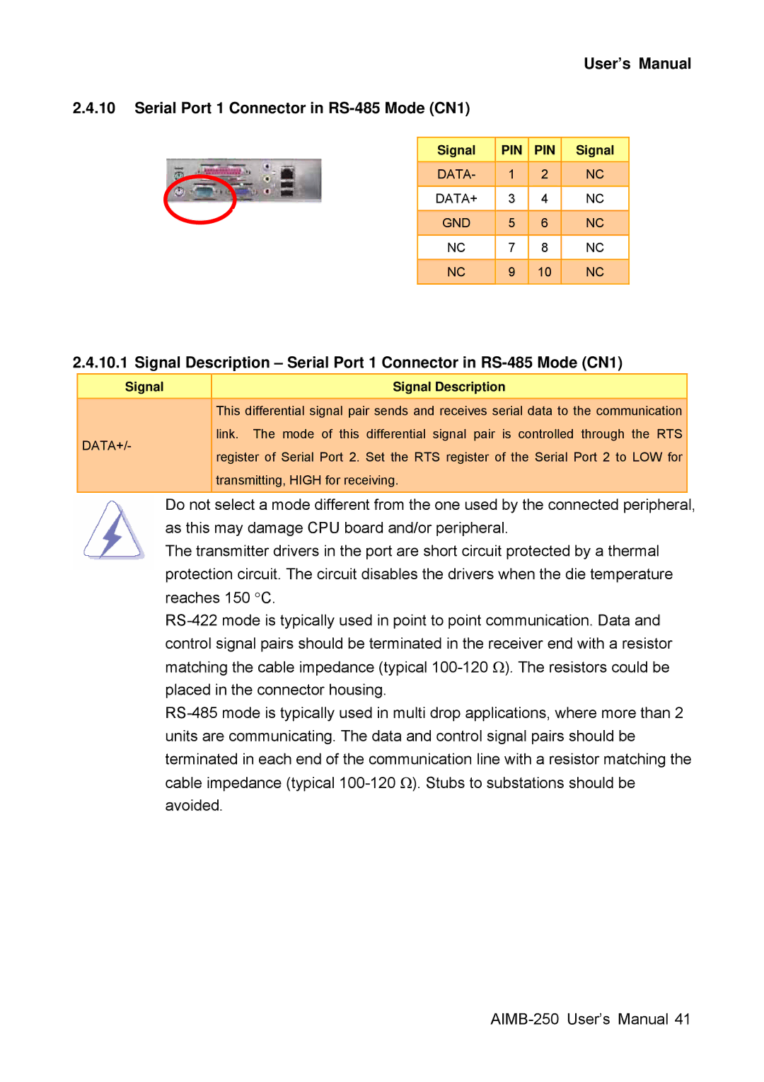
Serial Port 1 Connector in RS-485 Mode CN1
13 4/5/8-Wire Touch Screen Connector CN5, optional
AIMB-250 Series Audio Connector CN2 Audio-In
12 RJ-45 Ethernet / USB 0 & 1, 4 & 5 Connectors CN3, CN4
GND WPT Rdata SIDE1 Dskchg
User’s Manual Floppy Connector FLP1
Moatsa
AIMB-250 Series Signal Description Floppy Connector FLP
User’s Manual Primary IDE Connector IDE1
AIMB-250 Series Secondary IDE Connector IDE2
IOR#
RESET#
IOW#
Iordy
GND Enbkl
AIMB-250 Series LCD Inverter Connector JBKL1
Signal Description LCD Inverter Connector JBKL1
Serial Port 2 Connector JCOM1
User’s Manual CD-ROM Audio Input Connector JCD1
Signal Description CD-ROM Audio Input Connector JCD1
JCOM2 JCOM3
AIMB-250 Series Serial Port 3/4 Connector JCOM2, JCOM3
Signal Description Digital Input / Output Connector JDIO1
Digital Input / Output Connector JDIO1
Smbclk
Smbdata
HDD LED
AIMB-250 Series Front Panel Connector JFP1
Signal Description Front Panel Connecter JFP1
Signal Description IrDA Connecter JIR1
User’s Manual IrDA Connector JIR1
Irrx GND Irtx
Irrx
Signal Description Lvds Connector JLVDS1
AIMB-250 Series Lvds Connector JLVDS1
2CDAT 2CCLK GND
2CDAT, I 2CCLK
Signal Description Miscellaneous Setting Connecter JMISC1
User’s Manual Miscellaneous Setting Connector JMISC1
CASEOPEN# VTIN3 GND Thrmdn
#MASTER
Signal Description Tmds Connecter JTMDS1
AIMB-250 Series Tmds DVI Connector JTMDS1
Signal Description TV Out Connecter JTV1
User’s Manual TV Out Connector JTV1
Tvcvb GND TVYFCC2 TVCFCC2
Tvcvb
Signal Description USB Connecter 2, 3, 4 & 5 JUSB1, JUSB2
AIMB-250 Series USB Connector 2 & 3 JUSB1
USB Connector 4 & 5 JUSB2
Signal Description System Fan Connector SFAN1, SFAN2
System Fan Connector 1 & 2 SFAN1, SFAN2
Bios Setup
Press F1 to Continue, DEL to enter Setup
Starting Setup
Press DEL to enter Setup
Navigating Through The Menu Bar
Using Setup
User’s Manual To Display a Sub Menu
Case of Problems
Getting Help
Main Menu
Main Menu Selection
User’s Manual Standard Cmos Features
IDE Adapter Setup
CPU Feature
User’s Manual Advanced Bios Features
Quick Power On Self Test
Virus Warning
Boot Up NumLock Status Select power on state for NumLock
AIMB-250 Series First/Second/Third/Other Boot Device
Typematic Rate Setting
Swap Floppy Drive
MPS Version Control For OS
Apic Mode
OS Select for Dram 64MB
Report No FDD For WIN95
Active to Precharge Delay
AIMB-250 Series Advanced Chipset Features
Dram Timing Selectable
CAS Latency Time
Dram Data Integrity Mode
User’s Manual Dram RAS# to CAS# Delay
System Bios Cacheable
Video Bios Cacheable
Delay Prior to Thermal
Delayed Transaction
AIMB-250 Series Memory Hole At 15M-16M
AGP Aperture Size MB
OnChip IDE Device
User’s Manual Integrated Peripherals
IDE
Onboard Device
User’s Manual Super IO Device
2E8/IRQ3, Auto
Watch Dog Timer
ECP+EPP
IRQ3, IRQ4, IRQ5
Power Management
User’s Manual Power Management Setup
Acpi Function
Acpi Suspend Type
Resume By Alarm
Power On By Ring
AIMB-250 Series Modem Use IRQ
Soft-Off by PWR-BTTN
Reset Configuration Data
User’s Manual PnP / PCI Configuration
Resources Controlled By
PCI / VGA Palette Snoop
Case Open Warning
AIMB-250 Series PC Health Status
Auto Detect PCI Clk
User’s Manual Frequency / Voltage Control
Spread Spectrum
CPU Host / 3V66 / PCI Clock
Load Optimized Defaults
AIMB-250 Series Load Fail-Safe Defaults
User’s Manual Set Supervisor / User Password
Save & Exit Setup
Password Disabled
User’s Manual Exit Without Save
Drivers Installation
User’s Manual Click AIMB-250
Install Driver
Step
Mechanical Drawing
Unit mm
Award Bios Post
Post Beep
Error Messages
Overview
Eisa Configuration Is Not Complete
Eisa Configuration Checksum Error
Memory Address Error at
User’s Manual Invalid Eisa Configuration
Memory parity Error at
Memory Verify Error at
Slot Not Empty
Should Be Empty But Eisa Board Found
Should Have Eisa Board But Not Found
Bios ROM checksum error System halted
Keyboard error or no keyboard present
User’s Manual Wrong Board In Slot
Manufacturing Post loop
E1-EF
AIMB-250 Series Post Codes
40.1Normal Post Code
User’s Manual
AIMB-250 Series
User’s Manual
AIMB-250 Series
AIMB-250 User’s Manual101
AIMB-250 Series 40.2Quick Post Codes
AIMB-250 User’s Manual103
SMI
AIMB-250 Series 40.3S4 Post Codes
40.4BootBlock Post Codes