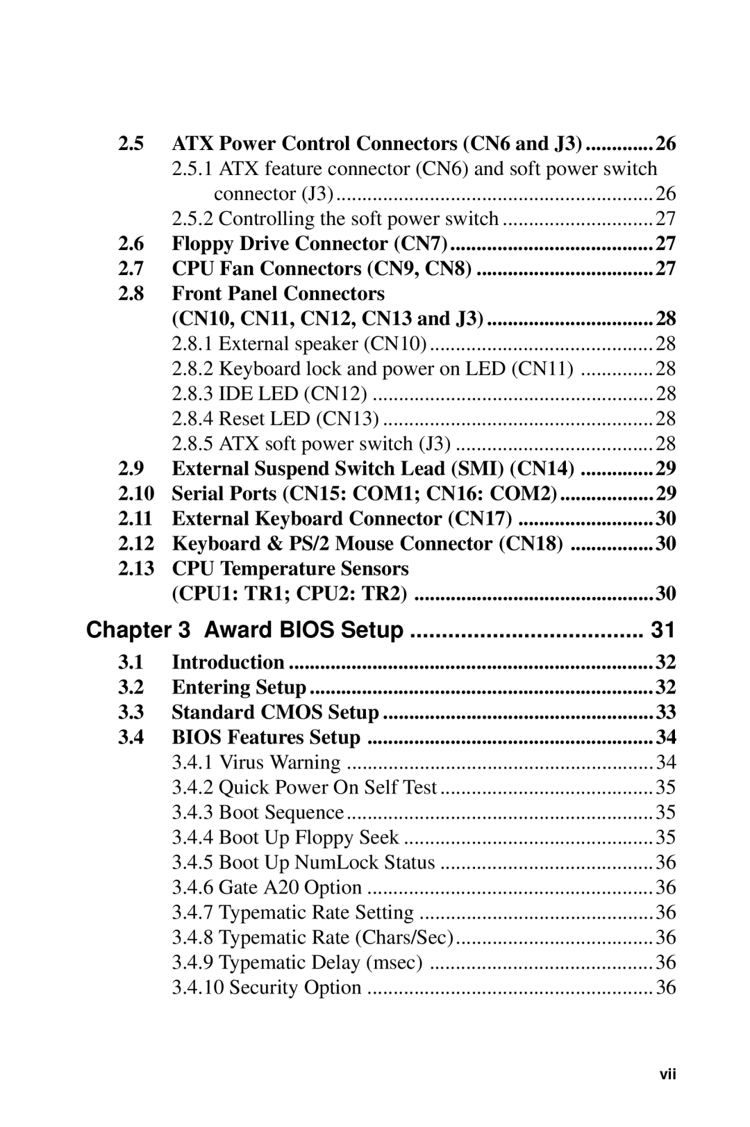
2.5 | ATX Power Control Connectors (CN6 and J3) | 26 |
| 2.5.1 ATX feature connector (CN6) and soft power switch | |
| connector (J3) | 26 |
| 2.5.2 Controlling the soft power switch | 27 |
2.6 | Floppy Drive Connector (CN7) | 27 |
2.7 | CPU Fan Connectors (CN9, CN8) | 27 |
2.8Front Panel Connectors
| (CN10, CN11, CN12, CN13 and J3) | 28 |
| 2.8.1 External speaker (CN10) | 28 |
| 2.8.2 Keyboard lock and power on LED (CN11) | 28 |
| 2.8.3 IDE LED (CN12) | 28 |
| 2.8.4 Reset LED (CN13) | 28 |
| 2.8.5 ATX soft power switch (J3) | 28 |
2.9 | External Suspend Switch Lead (SMI) (CN14) | 29 |
2.10 Serial Ports (CN15: COM1; CN16: COM2) | 29 | |
2.11 | External Keyboard Connector (CN17) | 30 |
2.12 Keyboard & PS/2 Mouse Connector (CN18) | 30 | |
2.13 | CPU Temperature Sensors |
|
| (CPU1: TR1; CPU2: TR2) | 30 |
Chapter 3 Award BIOS Setup | 31 | |
3.1 | Introduction | 32 |
3.2 | Entering Setup | 32 |
3.3 | Standard CMOS Setup | 33 |
3.4 | BIOS Features Setup | 34 |
| 3.4.1 Virus Warning | 34 |
| 3.4.2 Quick Power On Self Test | 35 |
| 3.4.3 Boot Sequence | 35 |
| 3.4.4 Boot Up Floppy Seek | 35 |
| 3.4.5 Boot Up NumLock Status | 36 |
| 3.4.6 Gate A20 Option | 36 |
| 3.4.7 Typematic Rate Setting | 36 |
| 3.4.8 Typematic Rate (Chars/Sec) | 36 |
| 3.4.9 Typematic Delay (msec) | 36 |
| 3.4.10 Security Option | 36 |
vii
