Additional Information
Attaching the external antenna connector
General setup information
When using a
VHF/UHF antenna, use the
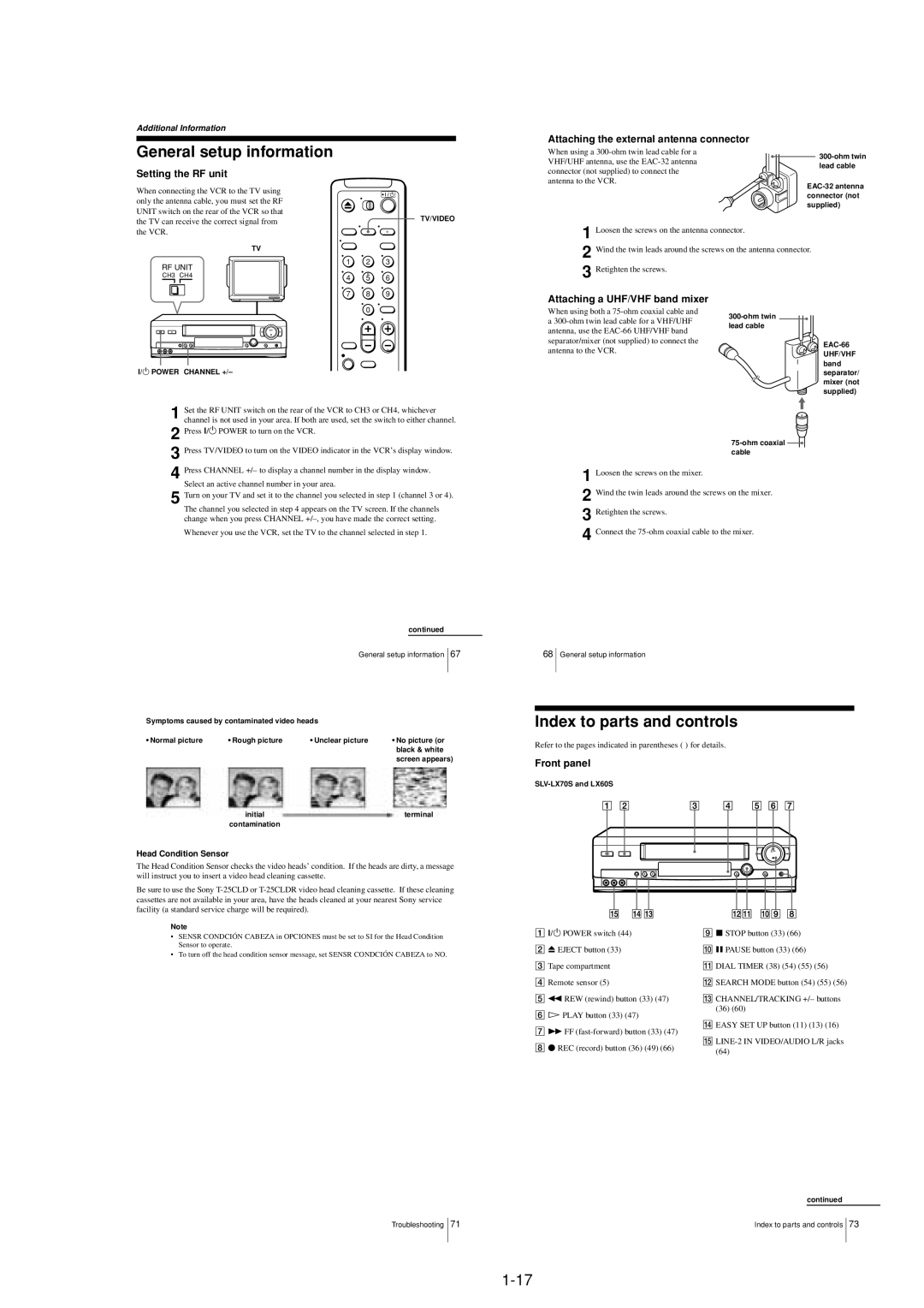
Setting the RF unit
connector (not supplied) to connect the
lead cable
When connecting the VCR to the TV using only the antenna cable, you must set the RF UNIT switch on the rear of the VCR so that the TV can receive the correct signal from the VCR.
TV
RF UNIT
CH3 CH4
TV/VIDEO
1 2 3
4 5 6
antenna to the VCR.
1 Loosen the screws on the antenna connector.
2 Wind the twin leads around the screws on the antenna connector.
3
7 8 9
0
Attaching a UHF/VHF band mixer
When using both a
UHF/VHF band
?/1 POWER CHANNEL +/–
1 Set the RF UNIT switch on the rear of the VCR to CH3 or CH4, whichever channel is not used in your area. If both are used, set the switch to either channel.
2 Press ?/1 POWER to turn on the VCR.
3 Press TV/VIDEO to turn on the VIDEO indicator in the VCR’s display window.
4 Press CHANNEL +/– to display a channel number in the display window. Select an active channel number in your area.
5 Turn on your TV and set it to the channel you selected in step 1 (channel 3 or 4). The channel you selected in step 4 appears on the TV screen. If the channels change when you press CHANNEL
Whenever you use the VCR, set the TV to the channel selected in step 1.
|
|
|
| continued | ||
|
| General setup information |
| 67 | ||
|
|
| ||||
Symptoms caused by contaminated video heads |
|
|
|
| ||
|
|
|
| |||
• Normal picture | • Rough picture | • Unclear picture | • No picture (or | |||
|
|
| black & white | |||
|
|
| screen appears) | |||
| initial |
| terminal | |||
| contamination |
|
|
|
|
|
Head Condition Sensor
The Head Condition Sensor checks the video heads’ condition. If the heads are dirty, a message will instruct you to insert a video head cleaning cassette.
Be sure to use the Sony
separator/ mixer (not supplied)
![]() cable
cable
1
2 Wind the twin leads around the screws on the mixer. 3 Retighten the screws.
4
68General setup information
Index to parts and controls
Refer to the pages indicated in parentheses ( ) for details.
Front panel
SLV-LX70S and LX60S
Note
•SENSR CONDCIÓN CABEZA in OPCIONES must be set to SI for the Head Condition Sensor to operate.
•To turn off the head condition sensor message, set SENSR CONDCIÓN CABEZA to NO.
A?/1 POWER switch (44)
BZ EJECT button (33)
CTape compartment
DRemote sensor (5)
Em REW (rewind) button (33) (47)
FH PLAY button (33) (47)
GM FF
Hz REC (record) button (36) (49) (66)
Ix STOP button (33) (66)
JX PAUSE button (33) (66)
KDIAL TIMER (38) (54) (55) (56)
LSEARCH MODE button (54) (55) (56)
MCHANNEL/TRACKING +/– buttons (36) (60)
NEASY SET UP button (11) (13) (16)
O
Troubleshooting 71
continued
Index to parts and controls 73