Specifications
RMT-V293A/V294A
Safety CHECK-OUT
Disassembly Adjustments
Table of Contents
Service Note
Block Diagrams
Service Note
Error Code Indication
Setting up the remote commander
Hookups
Completing A/V hookup
Hookup 1 VCR setup
Hookup Antenna hookup
Hookup
Hookup 3 VCR setup
Hookup 2 VCR setup
Hookup Connecting a cable box with many scrambled channels
Automatic clock setting
Setting the clock
Using the Auto Clock Set feature
Selecting a language
Using Manual Clock Set
If the clock does not activate
Presetting channels
Presetting all receivable channels automatically
Presetting/disabling channels manually
Playing a tape
If the picture is not clear
Recording TV programs
To save a recording
Recording TV programs using the Dial Timer
To watch another TV program while recording
Before you start
Recording TV programs using the timer
About the Demonstration Mode
To resume normal playback
Playing/searching at various speeds
Locking the VCR Child Lock
To lock the VCR
Recording stereo programs
Setting the recording duration time
Checking/changing/canceling timer settings
Recording bilingual programs
Searching using the Time Search function
Searching for the beginning of a timer recorded program
Searching using the index function
How sound is recorded on a video tape
To cancel skip-search
Search forward while Showing the tape contents Fast-forward
Press H Play or x Stop
Changing menu options
Adjusting the picture
Adjusting the tracking
About the Adaptive Picture Control APC function
Editing with another VCR
How to connect to record on this VCR
Operation when recording on this VCR
Before you start editing
General setup information
Index to parts and controls
Display window
Rear panel
11--19E
SLV-LX40/LX50/LX60S/LX70S Section Disassembly
CASE, Front Panel Block Assembly
Rear Panel
Mechansim Deck
Internal Views
Top View
Bottom View
Circuit Boards Location
Overall Block Diagram
Video Block Diagram
SERVO/SYSTEM Control Block Diagram
Tuner Block Diagram
Audio Block Diagram
Power Block Diagram
TA a
Xedit → Edit PB/XREC → PB/REC
Frame Schematic Diagram
VIDEO, AUDIO, SERVO/SYSTEM CONTROL, TUNER, Power
MA-405 REC/PB Head AMP Schematic Diagram
REC/PB Head AMP
See page 4-21 for waveforms MA-405 BOARD1/7
MA-405 Y/C, Audio Processor Schematic Diagram
Audio Process
Audio Processor VA Block
MA-405 SERVO/SYSTEM Control Schematic Diagram
SERVO/SYSTEM Control SS Block
MA-405 Audio Process Schematic Diagram
See page 4-5 for printed wiring board MA-405 BOARD4/7
Audio Process AU Block
Tuner
MA-405 Tuner Schematic Diagram
See page 4-5 for printed wiring board
MA-405 BOARD5/7
MA-405 Display Control Schematic Diagram
See page 4-5 for printed wiring board MA-405 BOARD6/7
Display Control Front Block
See page 4-5 for printed wiring board MA-405 BOARD7/7
Power Supply
MA-405 Power Supply Schematic Diagram
Power Supply PS Block
Drum PG
REC/PB
Drum FG
OSD V OUT
Line 2
FJ-32 Board
Line 2
Dial Timer
Dial Timer
DI-80 Board
Signal Pin No
System Control Mechanism Block Interface MA-405 Board IC160
System Control VIDEO/RP Block Interface MA-405 Board IC160
System Control Audio Block Interface MA-405 Board IC160
Pin Name Function
55-4E
Mechanical Adjustments
Electrical Adjustments
Preparation Before Adjustment
Power Supply Check
Input/Output Levels and Impedance
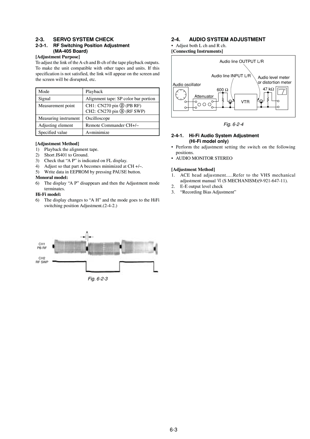
Audio System Adjustment
Servo System Check
VTR
ACE Head Adjustment
SW5V
Adjusting Parts Location Diagram
VIDEO/AUDIO Line IN/OUT
RF/HF SWP
Exploded Views
Front Panel and Upper Case Section
Chassis Section
5455
Mechanism Deck
707 708 712 706 702 701 709 704 710 705 722 703
721 711 720 713 725 724 714 719 715 717 718
Roller ASSY, Guide
Spring Power Tension
Brake ASSY,MAINT
Spring
803 802 833
Screw + P2.6 x 6 TYPE2 NON-SLIT
LX70SCL,CS Connector
Switch
SWITCH, Tact
Resistor
MA-405
Double Layer
Ceramic
Mylar
Film
HOUSING, Connector 6P LX40/LX50
CONNECTOR, FFC/FPC 5P
PIN, Connector 4P
CONNECTOR, FFC/FPC 7P
Short Jumper Selector
FILTER, Line Fluorescent Indicator Tube
TUBE, Fluorescent Indicator
Short Coil
Transistor 2SC1815GR-TPE2
Transistor
Transistor PT380F3
Transistor 2SC2712Y-TE85L
Metal Oxide
SWITCH, Tact Ppause
SWITCH, Rotary Mode
SWITCH, Tact 0REW
SWITCH, Tact ·PLAY
Ref. No Description Remarks Ref. No
Sony Corporation
Published by Quality Assurance Dept