TSC-40/IC Product Specification
4. Initial setting
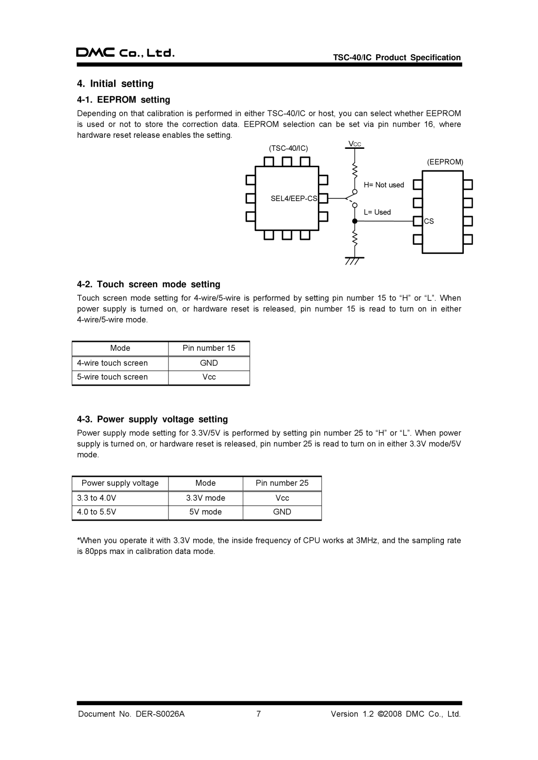
4-1. EEPROM setting
Depending on that calibration is performed in either
VCC
H= Not used
L= Used
(EEPROM)
CS
4-2. Touch screen mode setting
Touch screen mode setting for
Mode | Pin number 15 |
|
|
GND | |
|
|
Vcc | |
|
|
4-3. Power supply voltage setting
Power supply mode setting for 3.3V/5V is performed by setting pin number 25 to “H” or “L”. When power supply is turned on, or hardware reset is released, pin number 25 is read to turn on in either 3.3V mode/5V mode.
Power supply voltage | Mode | Pin number 25 |
|
|
|
3.3 to 4.0V | 3.3V mode | Vcc |
|
|
|
4.0 to 5.5V | 5V mode | GND |
|
|
|
*When you operate it with 3.3V mode, the inside frequency of CPU works at 3MHz, and the sampling rate is 80pps max in calibration data mode.
Document No. | 7 | Version 1.2 ©2008 DMC Co., Ltd. |