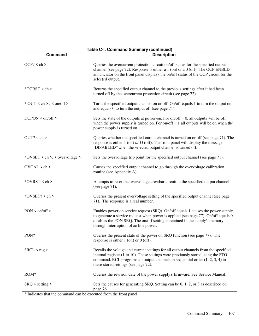
Table C-l. Command Summary (continued)

Command


Description

OCP? < ch >


Queries the overcurrent protection circuit on/off status for the specified output


channel (see page 72). Response is either a 1 (on) or a 0 (off). The OCP ENBLD


annunciator on the front panel displays the on/off status of the OCP circuit for the


selected output.

*OCRST < ch >


Returns the specified output channel to the previous settings after it had been


turned off by the overcurrent protection circuit (see page 72).

* OUT < ch > , < on/off >


Turns the specified output channel on or off. On/off equals 1 to turn the output on


and equals 0 to turn the output off (see page 71).

DCPON < on/off >


Sets the state of the outputs at power-on. For on/off = 0, all outputs will be off


when the power supply is turned on. For on/off = 1 all outputs will be on when the


power supply is turned on.

OUT? < ch >


Queries whether the specified output channel is turned on or off (see page 71). The


response is either 1 (on) or O (off). The front panel will display the message


’’DISABLED’’ when the selected output channel is turned off.


*OVSET < ch >, < overvoltage >

OVCAL < ch >

*OVRST < ch >

*OVSET? < ch >

PON < on/off >

Sets the overvoltage trip point for the specified output channel (see page 71).

Causes the specified output channel to go through the overvoltage calibration routine (see Appendix A).

Attempts to reset the overvoltage crowbar circuit in the specified output channel (see page 71).

Queries the present overvoltage setting of the specified output channel (see page 71). The response is a real number.

Enables power on service request (SRQ). On/off equals 1 causes the power supply to generate a service request when power is applied (see page 77). On/off equals 0 disables the PON SRQ. The on/off setting is retained in the supply’s memory through interruption of ac line power.

PON?

*RCL < reg >

Queries the present state of the power on SRQ function (see page 77). The response is either 1 (on) or 0 (off).

Recalls the voltage and current settings for all output channels from the specified internal register (1 to 10). These settings were previously stored using the STO command. RCL programs all output channels in sequential order (1, 2, 3, 4) to these stored settings (see page 72).

ROM?

Queries the revision date of the power supply’s firmware. See Service Manual.

SRQ < setting >

Sets the causes for generating SRQ. Setting can be 0, 1, 2, or 3 as described on


page 76.

* Indicates that the command can be executed from the front panel.

Command Summary 107

Page 101
Image 101
Agilent Technologies 6627A, 6621A, 6622A, 6623A, 6624A manual Pon?, Rom?

6627A, 6621A, 6624A, 6623A, 6622A specifications

Agilent Technologies is renowned for its high-quality electronic test and measurement equipment, and the Agilent 6600 series is no exception. This series includes models like the Agilent 6621A, 6622A, 6623A, 6624A, and 6627A, each designed to meet the needs of various application requirements, making them an essential part of modern laboratories.

The Agilent 6621A is a single-output DC power supply that provides a stable output voltage and current, making it ideal for testing and powering electronic devices. It features a low noise specification, which is crucial for sensitive applications. With a maximum output voltage of 30V and a current of 3A, it offers flexibility for a range of projects, from powering prototypes to performing benchmark tests.

The Agilent 6622A, a dual-output model, enhances versatility by allowing users to power two devices concurrently. It delivers output voltages of up to 20V and a total output current of 5A, which is perfect for powering circuit boards with multiple components. The built-in voltage and current limiting functions protect the equipment under test, preventing any potential damage.

On the other hand, the Agilent 6623A provides additional capabilities with its three outputs, making it particularly suitable for complex testing procedures. With a maximum voltage of 20V and output current reaching 6A across all channels, it ensures that multiple loads can be powered simultaneously without compromising performance.

The Agilent 6624A further pushes these capabilities with its higher output power. This model boasts two outputs with a combined maximum output of up to 6A, supporting devices that require more demanding power levels. Its advanced control features allow for precise voltage and current adjustments, enhancing reliability during experiments.

Lastly, the Agilent 6627A stands out as a highly scalable power supply, capable of delivering up to 40V and 7.5A across its multiple outputs. This model is particularly beneficial for applications requiring higher voltages, enabling engineers and technicians to work with a broader array of components and systems.

All models in the Agilent 6600 series incorporate built-in protection features to guarantee safety during testing. They are equipped with memory functions, allowing users to save and recall settings quickly. Additionally, the intuitive interface and various connectivity options make these power supplies user-friendly, ensuring efficient workflow in any laboratory setting. In summary, the Agilent 6600 series offers a compelling combination of versatility, precision, and advanced features, catering to diverse electronic testing applications.