6627A, 6621A, 6624A, 6623A, 6622A specifications
Agilent Technologies is renowned for its high-quality electronic test and measurement equipment, and the Agilent 6600 series is no exception. This series includes models like the Agilent 6621A, 6622A, 6623A, 6624A, and 6627A, each designed to meet the needs of various application requirements, making them an essential part of modern laboratories.The Agilent 6621A is a single-output DC power supply that provides a stable output voltage and current, making it ideal for testing and powering electronic devices. It features a low noise specification, which is crucial for sensitive applications. With a maximum output voltage of 30V and a current of 3A, it offers flexibility for a range of projects, from powering prototypes to performing benchmark tests.
The Agilent 6622A, a dual-output model, enhances versatility by allowing users to power two devices concurrently. It delivers output voltages of up to 20V and a total output current of 5A, which is perfect for powering circuit boards with multiple components. The built-in voltage and current limiting functions protect the equipment under test, preventing any potential damage.
On the other hand, the Agilent 6623A provides additional capabilities with its three outputs, making it particularly suitable for complex testing procedures. With a maximum voltage of 20V and output current reaching 6A across all channels, it ensures that multiple loads can be powered simultaneously without compromising performance.
The Agilent 6624A further pushes these capabilities with its higher output power. This model boasts two outputs with a combined maximum output of up to 6A, supporting devices that require more demanding power levels. Its advanced control features allow for precise voltage and current adjustments, enhancing reliability during experiments.
Lastly, the Agilent 6627A stands out as a highly scalable power supply, capable of delivering up to 40V and 7.5A across its multiple outputs. This model is particularly beneficial for applications requiring higher voltages, enabling engineers and technicians to work with a broader array of components and systems.
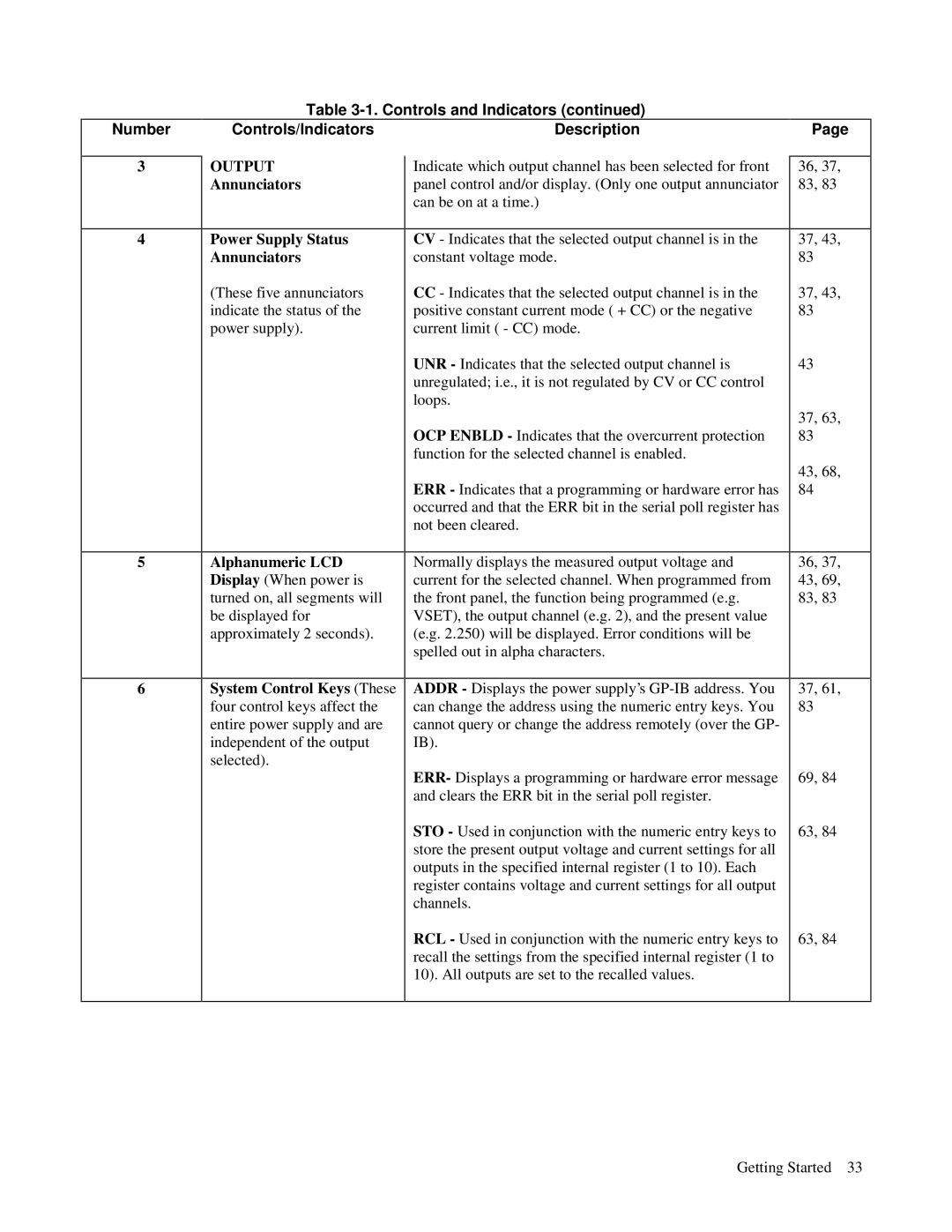
All models in the Agilent 6600 series incorporate built-in protection features to guarantee safety during testing. They are equipped with memory functions, allowing users to save and recall settings quickly. Additionally, the intuitive interface and various connectivity options make these power supplies user-friendly, ensuring efficient workflow in any laboratory setting. In summary, the Agilent 6600 series offers a compelling combination of versatility, precision, and advanced features, catering to diverse electronic testing applications.

