NOTES:

1.Output channels 3 and 4 are not used in all models. (See Table 5-4).

2.Applies to 80 W Low V output.

3.Applies to 40 W High V and 80 W High V outputs.

4.’’X’’ depends upon model.

5.A space is returned for a + sign.

6.All responses are followed by a < CR > and < LF > (EOI asserted with < LF > ).

7.Spaces are allowed between the header and the question mark.

Order of Execution

When you send a set of instructions to the power supply, they are executed in the order in which they are received. The power supply completes the execution of the present command before executing another command. To send more than one command within the power supply command string, use a semicolon to separate the commands. This maximizes the rate at which the power supply accepts commands.

Terminators

Terminators mark the end of a command string. As shown in Figure 5-2, the semicolon, line feed < LF >, and carriage return line feed < CR > < LF > are the characters that indicate the end of a message to the power supply. When you are using the Agilent Series 200 computer with BASIC to send a command using the standard format (see Figure 5-1), the computer automatically sends < CR > < LF > on the data bus following the command.

Initial Conditions

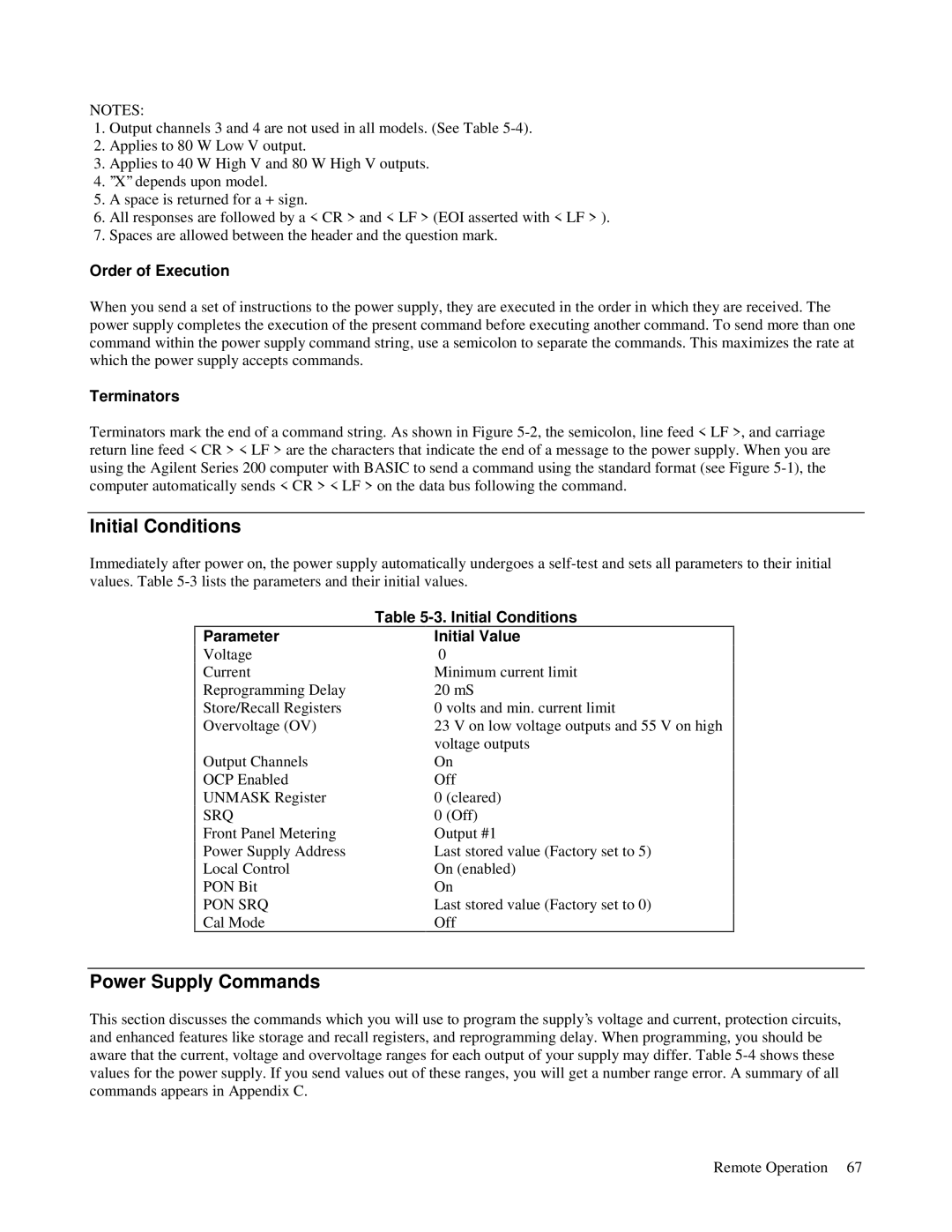
Immediately after power on, the power supply automatically undergoes a self-test and sets all parameters to their initial values. Table 5-3 lists the parameters and their initial values.


Table 5-3. Initial Conditions

Parameter


Initial Value

Voltage

0

Current


Minimum current limit

Reprogramming Delay


20 mS

Store/Recall Registers


0 volts and min. current limit

Overvoltage (OV)


23 V on low voltage outputs and 55 V on high


voltage outputs

Output Channels


On

OCP Enabled


Off

UNMASK Register


0 (cleared)

SRQ


0 (Off)

Front Panel Metering


Output #1

Power Supply Address


Last stored value (Factory set to 5)

Local Control


On (enabled)

PON Bit


On

PON SRQ


Last stored value (Factory set to 0)

Cal Mode


Off

Power Supply Commands

This section discusses the commands which you will use to program the supply’s voltage and current, protection circuits, and enhanced features like storage and recall registers, and reprogramming delay. When programming, you should be aware that the current, voltage and overvoltage ranges for each output of your supply may differ. Table 5-4 shows these values for the power supply. If you send values out of these ranges, you will get a number range error. A summary of all commands appears in Appendix C.

Remote Operation 67

Page 64
Image 64
Agilent Technologies 6624A, 6621A, 6627A, 6622A, 6623A manual Initial Conditions, Power Supply Commands

6627A, 6621A, 6624A, 6623A, 6622A specifications

Agilent Technologies is renowned for its high-quality electronic test and measurement equipment, and the Agilent 6600 series is no exception. This series includes models like the Agilent 6621A, 6622A, 6623A, 6624A, and 6627A, each designed to meet the needs of various application requirements, making them an essential part of modern laboratories.

The Agilent 6621A is a single-output DC power supply that provides a stable output voltage and current, making it ideal for testing and powering electronic devices. It features a low noise specification, which is crucial for sensitive applications. With a maximum output voltage of 30V and a current of 3A, it offers flexibility for a range of projects, from powering prototypes to performing benchmark tests.

The Agilent 6622A, a dual-output model, enhances versatility by allowing users to power two devices concurrently. It delivers output voltages of up to 20V and a total output current of 5A, which is perfect for powering circuit boards with multiple components. The built-in voltage and current limiting functions protect the equipment under test, preventing any potential damage.

On the other hand, the Agilent 6623A provides additional capabilities with its three outputs, making it particularly suitable for complex testing procedures. With a maximum voltage of 20V and output current reaching 6A across all channels, it ensures that multiple loads can be powered simultaneously without compromising performance.

The Agilent 6624A further pushes these capabilities with its higher output power. This model boasts two outputs with a combined maximum output of up to 6A, supporting devices that require more demanding power levels. Its advanced control features allow for precise voltage and current adjustments, enhancing reliability during experiments.

Lastly, the Agilent 6627A stands out as a highly scalable power supply, capable of delivering up to 40V and 7.5A across its multiple outputs. This model is particularly beneficial for applications requiring higher voltages, enabling engineers and technicians to work with a broader array of components and systems.

All models in the Agilent 6600 series incorporate built-in protection features to guarantee safety during testing. They are equipped with memory functions, allowing users to save and recall settings quickly. Additionally, the intuitive interface and various connectivity options make these power supplies user-friendly, ensuring efficient workflow in any laboratory setting. In summary, the Agilent 6600 series offers a compelling combination of versatility, precision, and advanced features, catering to diverse electronic testing applications.