Enabling/Disabling an Output

The selected output channel can be turned on and off from the front panel. The OUTPUT ON/OFF key toggles the selected output on and off. When an output is turned off, the message ’’DISABLED" will be displayed.

The OUTPUT ON/OFF key will not affect any other programmed functions nor will it reset an overvoltage or overcurrent condition. An output disabled by the OUTPUT ON/OFF key will behave as if it were programmed to zero volts and minimum current.

Setting Overvoltage Protection

Programmable overvoltage protection (OVP) guards your load against overvoltage by crowbarring and downprogramming the power supply output if the programmed overvoltage setting is exceeded.

A fixed OVP circuit with a trip level about 20 percent above the maximum programmable voltage acts as a backup to the programmable OVP. When overvoltage protection is activated, the output is shorted and the message ’’OVERVOLTAGE" will appear on the front panel display.

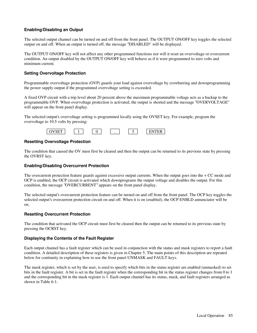
The selected output’s overvoltage setting is programmed locally using the OVSET key. For example, program the overvoltage to 10.5 volts by pressing:

OVSET

1

0

.

5

ENTER

Resetting Overvoltage Protection

The condition that caused the OV must first be cleared and then the output can be returned to its previous state by pressing the OVRST key.

Enabling/Disabling Overcurrent Protection

The overcurrent protection feature guards against excessive output currents. When the output goes into the + CC mode and OCP is enabled, the OCP circuit is activated which downprograms the output voltage and disables the output. For this condition, the message ’’OVERCURRENT’’ appears on the front panel display.

The selected output’s overcurrent protection feature can be turned on and off from the front panel. The OCP key toggles the selected output’s overcurrent protection circuit on and off. When it is on (enabled), the OCP ENBLD annunciator will be on.

Resetting Overcurrent Protection

The condition that activated the OCP circuit must first be cleared then the output can be returned to its previous state by pressing the OCRST key.

Displaying the Contents of the Fault Register

Each output channel has a fault register which can be used in conjunction with the status and mask registers to report a fault condition. A detailed description of these registers is given in Chapter 5. The main points of this description are repeated below for continuity in explaining how to use the front panel UNMASK and FAULT keys.

The mask register, which is set by the user, is used to specify which bits in the status register are enabled (unmasked) to set bits in the fault register. A bit is set in the fault register when the corresponding bit in the status register changes from 0 to 1 and the corresponding bit in the mask register is 1. Each output channel has its status, mask, and fault registers arranged as shown in Table 6-1.

Local Operation 85

Page 81
Image 81
Agilent Technologies 6627A Enabling/Disabling an Output, Setting Overvoltage Protection, Resetting Overvoltage Protection

6627A, 6621A, 6624A, 6623A, 6622A specifications

Agilent Technologies is renowned for its high-quality electronic test and measurement equipment, and the Agilent 6600 series is no exception. This series includes models like the Agilent 6621A, 6622A, 6623A, 6624A, and 6627A, each designed to meet the needs of various application requirements, making them an essential part of modern laboratories.

The Agilent 6621A is a single-output DC power supply that provides a stable output voltage and current, making it ideal for testing and powering electronic devices. It features a low noise specification, which is crucial for sensitive applications. With a maximum output voltage of 30V and a current of 3A, it offers flexibility for a range of projects, from powering prototypes to performing benchmark tests.

The Agilent 6622A, a dual-output model, enhances versatility by allowing users to power two devices concurrently. It delivers output voltages of up to 20V and a total output current of 5A, which is perfect for powering circuit boards with multiple components. The built-in voltage and current limiting functions protect the equipment under test, preventing any potential damage.

On the other hand, the Agilent 6623A provides additional capabilities with its three outputs, making it particularly suitable for complex testing procedures. With a maximum voltage of 20V and output current reaching 6A across all channels, it ensures that multiple loads can be powered simultaneously without compromising performance.

The Agilent 6624A further pushes these capabilities with its higher output power. This model boasts two outputs with a combined maximum output of up to 6A, supporting devices that require more demanding power levels. Its advanced control features allow for precise voltage and current adjustments, enhancing reliability during experiments.

Lastly, the Agilent 6627A stands out as a highly scalable power supply, capable of delivering up to 40V and 7.5A across its multiple outputs. This model is particularly beneficial for applications requiring higher voltages, enabling engineers and technicians to work with a broader array of components and systems.

All models in the Agilent 6600 series incorporate built-in protection features to guarantee safety during testing. They are equipped with memory functions, allowing users to save and recall settings quickly. Additionally, the intuitive interface and various connectivity options make these power supplies user-friendly, ensuring efficient workflow in any laboratory setting. In summary, the Agilent 6600 series offers a compelling combination of versatility, precision, and advanced features, catering to diverse electronic testing applications.