470 !

480IF FNPs _ err < >0 THEN Finish

490!

500OUTPUT @Ps;"VSET ";Chan,"0 ;ISET ’’;Chan,"0"

510!

520INPUT "ANY MORE OUTPUTS TO CALIBRATE? (Y OR N)",X$

530IF (X$=’’Y" OR X$=’’y") THEN Start_loop

540!

550OUTPUT @Ps;"CMODE 0"

560!

570Finish: ! HERE WHEN DONE

580OUTPUT @Ps;’’CLR"

590DISP "END OF CALIBRATION PROGRAM"

600END

610!

620!

630DEF FNDvm

640COM /Instr/ (@Ps,@Vm

650WAIT.02

660TRIGGER @Vm

670ENTER @Vm;Reading

680RETURN Reading

690FNEND

700!

710DEF FNPs _ err

720COM /Instr/ @Ps,@Vrn

730OUTPUT @Ps;’’ERR?"

740ENTER @Ps;Err

750IF Err< >0 THEN PRINT "POWER SUPPLY ERROR # '';Err;" CORRECTION CONSTANTS NOT SAVED - RESTART. "

760RETURN Err

770FNEND

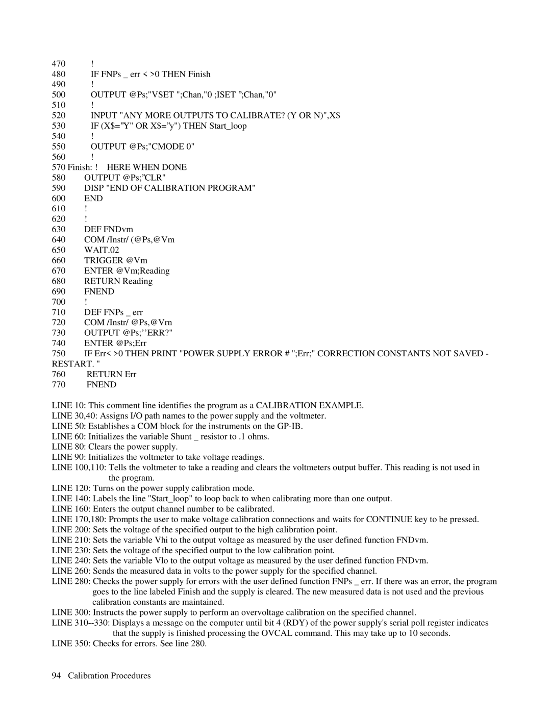
LINE 10: This comment line identifies the program as a CALIBRATION EXAMPLE.

LINE 30,40: Assigns I/O path names to the power supply and the voltmeter.

LINE 50: Establishes a COM block for the instruments on the GP-IB.

LINE 60: Initializes the variable Shunt _ resistor to .1 ohms.

LINE 80: Clears the power supply.

LINE 90: Initializes the voltmeter to take voltage readings.

LINE 100,110: Tells the voltmeter to take a reading and clears the voltmeters output buffer. This reading is not used in the program.

LINE 120: Turns on the power supply calibration mode.

LINE 140: Labels the line ''Start_loop" to loop back to when calibrating more than one output.

LINE 160: Enters the output channel number to be calibrated.

LINE 170,180: Prompts the user to make voltage calibration connections and waits for CONTINUE key to be pressed.

LINE 200: Sets the voltage of the specified output to the high calibration point.

LINE 210: Sets the variable Vhi to the output voltage as measured by the user defined function FNDvm.

LINE 230: Sets the voltage of the specified output to the low calibration point.

LINE 240: Sets the variable Vlo to the output voltage as measured by the user defined function FNDvm.

LINE 260: Sends the measured data in volts to the power supply for the specified channel.

LINE 280: Checks the power supply for errors with the user defined function FNPs _ err. If there was an error, the program goes to the line labeled Finish and the supply is cleared. The new measured data is not used and the previous calibration constants are maintained.

LINE 300: Instructs the power supply to perform an overvoltage calibration on the specified channel.

LINE 310--330: Displays a message on the computer until bit 4 (RDY) of the power supply's serial poll register indicates that the supply is finished processing the OVCAL command. This may take up to 10 seconds.

LINE 350: Checks for errors. See line 280.

94 Calibration Procedures

Page 89
Image 89
Agilent Technologies 6624A, 6621A Input ANY More Outputs to CALIBRATE? Y or N,X$, Disp END of Calibration Program, Fnend

6627A, 6621A, 6624A, 6623A, 6622A specifications

Agilent Technologies is renowned for its high-quality electronic test and measurement equipment, and the Agilent 6600 series is no exception. This series includes models like the Agilent 6621A, 6622A, 6623A, 6624A, and 6627A, each designed to meet the needs of various application requirements, making them an essential part of modern laboratories.

The Agilent 6621A is a single-output DC power supply that provides a stable output voltage and current, making it ideal for testing and powering electronic devices. It features a low noise specification, which is crucial for sensitive applications. With a maximum output voltage of 30V and a current of 3A, it offers flexibility for a range of projects, from powering prototypes to performing benchmark tests.

The Agilent 6622A, a dual-output model, enhances versatility by allowing users to power two devices concurrently. It delivers output voltages of up to 20V and a total output current of 5A, which is perfect for powering circuit boards with multiple components. The built-in voltage and current limiting functions protect the equipment under test, preventing any potential damage.

On the other hand, the Agilent 6623A provides additional capabilities with its three outputs, making it particularly suitable for complex testing procedures. With a maximum voltage of 20V and output current reaching 6A across all channels, it ensures that multiple loads can be powered simultaneously without compromising performance.

The Agilent 6624A further pushes these capabilities with its higher output power. This model boasts two outputs with a combined maximum output of up to 6A, supporting devices that require more demanding power levels. Its advanced control features allow for precise voltage and current adjustments, enhancing reliability during experiments.

Lastly, the Agilent 6627A stands out as a highly scalable power supply, capable of delivering up to 40V and 7.5A across its multiple outputs. This model is particularly beneficial for applications requiring higher voltages, enabling engineers and technicians to work with a broader array of components and systems.

All models in the Agilent 6600 series incorporate built-in protection features to guarantee safety during testing. They are equipped with memory functions, allowing users to save and recall settings quickly. Additionally, the intuitive interface and various connectivity options make these power supplies user-friendly, ensuring efficient workflow in any laboratory setting. In summary, the Agilent 6600 series offers a compelling combination of versatility, precision, and advanced features, catering to diverse electronic testing applications.