General Characteristics
RS-232 connector
This male
Pin number |
| Signal description | Signal name | ||
1 |
|
| No connection |
| |
2 |
|
| Receive data | RECV | |
3 |
|
| Transmit data | XMIT | |
4 |
|
| +5 V |
|
|
5 |
|
| Ground, 0 V |
| |
6 |
|
| No connection |
| |
7 |
|
| Request to send | RTS | |
8 |
|
| Clear to send | CTS | |
9 |
|
| No connection |
| |
|
|
|
|
|
|
5 | 4 | 3 | 2 | 1 |
|
| 9 | 8 | 7 | 6 |
|
View looking into rear panel connector
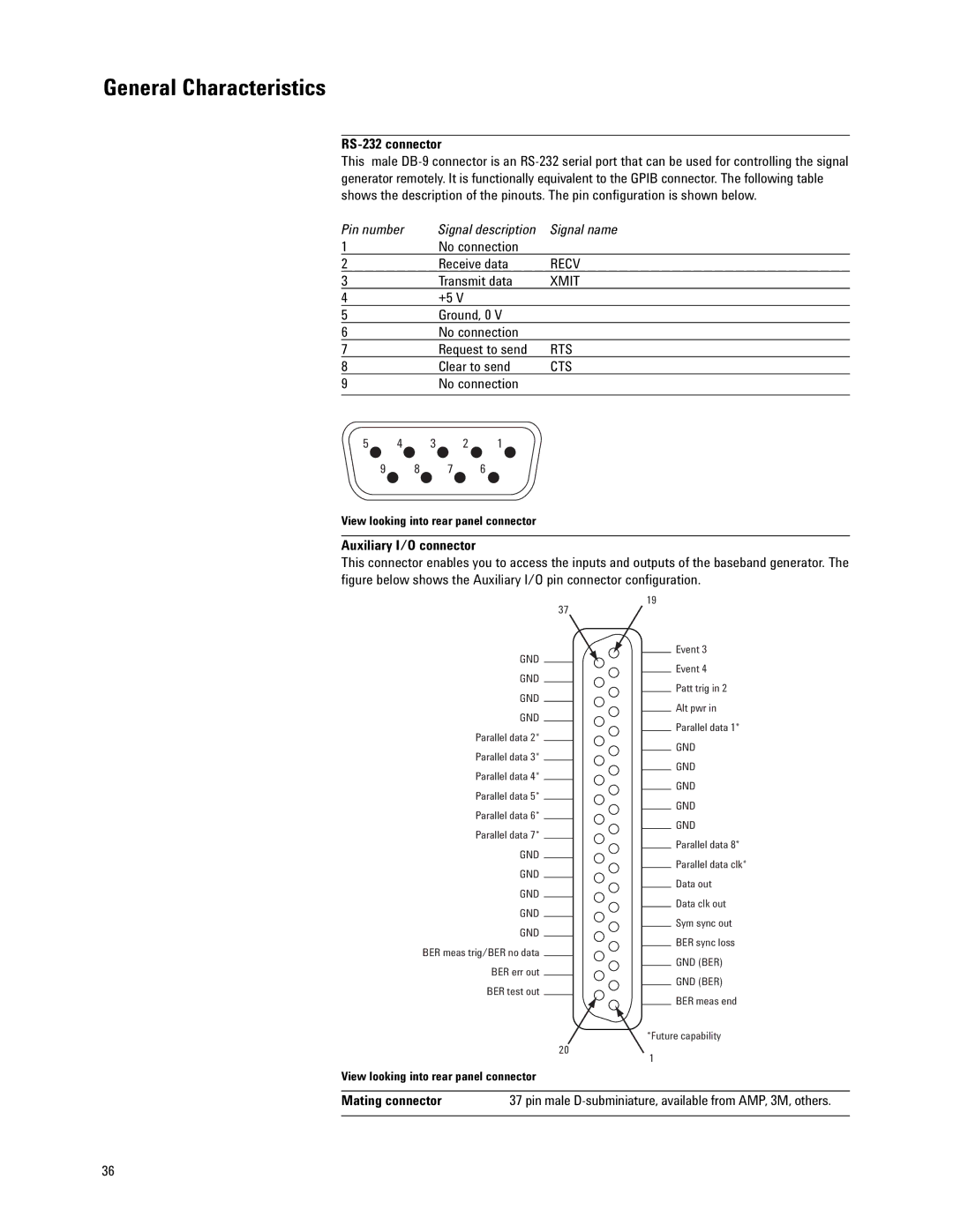
Auxiliary I/O connector
This connector enables you to access the inputs and outputs of the baseband generator. The figure below shows the Auxiliary I/O pin connector configuration.
19
37
Event 3
GND
Event 4
GND
Patt trig in 2
GND
Alt pwr in
GND
Parallel data 1*
Parallel data 2*
GND
Parallel data 3*
GND
Parallel data 4*
GND
Parallel data 5*
GND
Parallel data 6*
GND
Parallel data 7*
Parallel data 8*
GND
Parallel data clk*
GND
Data out
GND
Data clk out
GND
Sym sync out
GND
BER sync loss
BER meas trig/BER no data
GND (BER)
BER err out
GND (BER)
BER test out
BER meas end
*Future capability
20
1
View looking into rear panel connector
Mating connector | 37 pin male |
|
|
36