Contents

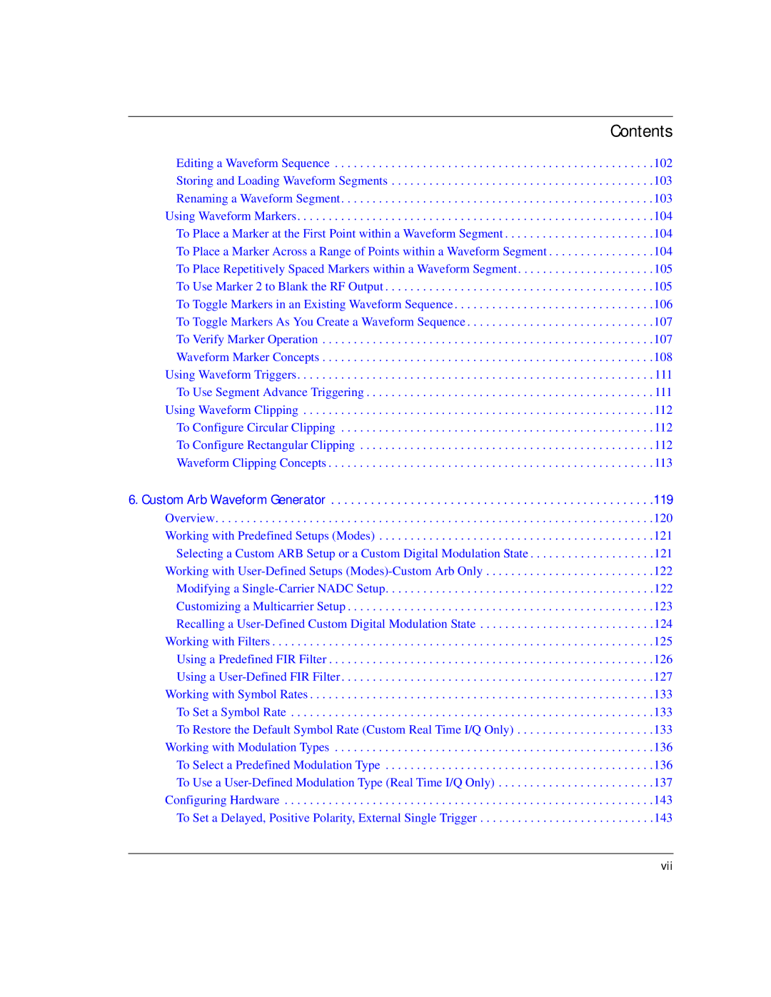
Editing a Waveform Sequence . . . . . . . . . . . . . . . . . . . . . . . . . . . . . . . . . . . . . . . . . . . . . . . . . . .102 Storing and Loading Waveform Segments . . . . . . . . . . . . . . . . . . . . . . . . . . . . . . . . . . . . . . . . . .103 Renaming a Waveform Segment . . . . . . . . . . . . . . . . . . . . . . . . . . . . . . . . . . . . . . . . . . . . . . . . . .103 Using Waveform Markers. . . . . . . . . . . . . . . . . . . . . . . . . . . . . . . . . . . . . . . . . . . . . . . . . . . . . . . . .104 To Place a Marker at the First Point within a Waveform Segment . . . . . . . . . . . . . . . . . . . . . . . .104 To Place a Marker Across a Range of Points within a Waveform Segment . . . . . . . . . . . . . . . . .104 To Place Repetitively Spaced Markers within a Waveform Segment. . . . . . . . . . . . . . . . . . . . . .105 To Use Marker 2 to Blank the RF Output . . . . . . . . . . . . . . . . . . . . . . . . . . . . . . . . . . . . . . . . . . .105 To Toggle Markers in an Existing Waveform Sequence . . . . . . . . . . . . . . . . . . . . . . . . . . . . . . . .106 To Toggle Markers As You Create a Waveform Sequence . . . . . . . . . . . . . . . . . . . . . . . . . . . . . .107 To Verify Marker Operation . . . . . . . . . . . . . . . . . . . . . . . . . . . . . . . . . . . . . . . . . . . . . . . . . . . . .107 Waveform Marker Concepts . . . . . . . . . . . . . . . . . . . . . . . . . . . . . . . . . . . . . . . . . . . . . . . . . . . . .108 Using Waveform Triggers. . . . . . . . . . . . . . . . . . . . . . . . . . . . . . . . . . . . . . . . . . . . . . . . . . . . . . . . . 111 To Use Segment Advance Triggering . . . . . . . . . . . . . . . . . . . . . . . . . . . . . . . . . . . . . . . . . . . . . . 111 Using Waveform Clipping . . . . . . . . . . . . . . . . . . . . . . . . . . . . . . . . . . . . . . . . . . . . . . . . . . . . . . . . 112 To Configure Circular Clipping . . . . . . . . . . . . . . . . . . . . . . . . . . . . . . . . . . . . . . . . . . . . . . . . . . 112 To Configure Rectangular Clipping . . . . . . . . . . . . . . . . . . . . . . . . . . . . . . . . . . . . . . . . . . . . . . . 112 Waveform Clipping Concepts . . . . . . . . . . . . . . . . . . . . . . . . . . . . . . . . . . . . . . . . . . . . . . . . . . . . 113

6. Custom Arb Waveform Generator . . . . . . . . . . . . . . . . . . . . . . . . . . . . . . . . . . . . . . . . . . . . . . . . .119

Overview. . . . . . . . . . . . . . . . . . . . . . . . . . . . . . . . . . . . . . . . . . . . . . . . . . . . . . . . . . . . . . . . . . . . . .120 Working with Predefined Setups (Modes) . . . . . . . . . . . . . . . . . . . . . . . . . . . . . . . . . . . . . . . . . . . .121 Selecting a Custom ARB Setup or a Custom Digital Modulation State . . . . . . . . . . . . . . . . . . . .121 Working with User-Defined Setups (Modes)-Custom Arb Only . . . . . . . . . . . . . . . . . . . . . . . . . . .122 Modifying a Single-Carrier NADC Setup. . . . . . . . . . . . . . . . . . . . . . . . . . . . . . . . . . . . . . . . . . .122 Customizing a Multicarrier Setup . . . . . . . . . . . . . . . . . . . . . . . . . . . . . . . . . . . . . . . . . . . . . . . . .123 Recalling a User-Defined Custom Digital Modulation State . . . . . . . . . . . . . . . . . . . . . . . . . . . .124 Working with Filters . . . . . . . . . . . . . . . . . . . . . . . . . . . . . . . . . . . . . . . . . . . . . . . . . . . . . . . . . . . . .125 Using a Predefined FIR Filter . . . . . . . . . . . . . . . . . . . . . . . . . . . . . . . . . . . . . . . . . . . . . . . . . . . .126 Using a User-Defined FIR Filter . . . . . . . . . . . . . . . . . . . . . . . . . . . . . . . . . . . . . . . . . . . . . . . . . .127 Working with Symbol Rates . . . . . . . . . . . . . . . . . . . . . . . . . . . . . . . . . . . . . . . . . . . . . . . . . . . . . . .133 To Set a Symbol Rate . . . . . . . . . . . . . . . . . . . . . . . . . . . . . . . . . . . . . . . . . . . . . . . . . . . . . . . . . .133 To Restore the Default Symbol Rate (Custom Real Time I/Q Only) . . . . . . . . . . . . . . . . . . . . . .133 Working with Modulation Types . . . . . . . . . . . . . . . . . . . . . . . . . . . . . . . . . . . . . . . . . . . . . . . . . . .136 To Select a Predefined Modulation Type . . . . . . . . . . . . . . . . . . . . . . . . . . . . . . . . . . . . . . . . . . .136 To Use a User-Defined Modulation Type (Real Time I/Q Only) . . . . . . . . . . . . . . . . . . . . . . . . .137 Configuring Hardware . . . . . . . . . . . . . . . . . . . . . . . . . . . . . . . . . . . . . . . . . . . . . . . . . . . . . . . . . . .143 To Set a Delayed, Positive Polarity, External Single Trigger . . . . . . . . . . . . . . . . . . . . . . . . . . . .143

vii

Page 7
Image 7
Agilent Technologies E8247C PSG CW, E8267C PSG, E8257C PSG manual Vii

E8267C PSG, E8247C PSG CW, E8257C PSG specifications

Agilent Technologies, a leading provider of electronic test and measurement equipment, offers a range of signal generators that are pivotal in various applications, including telecommunications, aerospace, and research. Among their top-tier offerings are the E8257C PSG, E8247C PSG CW, and E8267C PSG. These signal generators are known for their exceptional performance, flexibility, and cutting-edge technologies.

The E8257C PSG is a high-performance microwave signal generator capable of generating signals from 10 MHz to 40 GHz. Its versatility makes it ideal for applications such as radar and satellite communications. One of the standout features of the E8257C is its low phase noise and superior output power, which ensure high-quality signal generation. The instrument incorporates advanced digital signal processing technology, allowing users to create complex modulated signals with precision. It also boasts a comprehensive set of modulation formats, including AM, FM, PM, and pulse modulation, making it suitable for diverse testing scenarios.

The E8247C PSG CW is designed specifically for continuous wave (CW) applications, covering frequencies from 500 kHz to 20 GHz. This generator is optimized for high stability and low output noise, making it ideal for applications that require a reliable signal source, such as manufacturing testing and maintenance of communication systems. The E8247C features a compact design and is equipped with an intuitive user interface, allowing quick access to essential functions. Its frequency agility and fast switching capabilities enhance productivity, enabling engineers to optimize their workflow.

The E8267C PSG delivers unparalleled performance in the microwave frequency range of 250 kHz to 70 GHz. It includes advanced modulation capabilities, allowing users to generate complex waveforms with relative ease. The E8267C supports various digital modulation schemes, including QAM, which is crucial for testing modern communication systems. Its high output power and excellent spectral purity make it suitable for both R&D and manufacturing applications. Additionally, the E8267C features built-in functionality for frequency and power sweeps, providing users with extensive testing options.

In summary, Agilent Technologies’ E8257C, E8247C, and E8267C signal generators are integral tools for professionals seeking high performance and versatility in their testing environments. With unique features and advanced technologies, these generators cater to the demands of modern applications, ensuring reliable and accurate signal generation for a wide range of industries. Whether it's for research, development, or manufacturing, these instruments demonstrate Agilent's commitment to delivering top-notch testing solutions.