Appendix
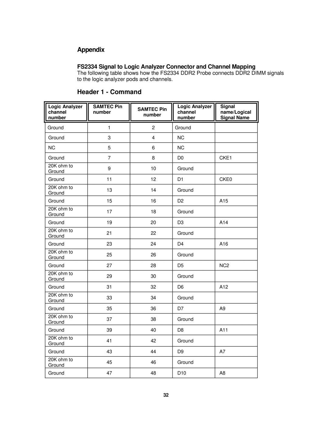
FS2334 Signal to Logic Analyzer Connector and Channel Mapping
The following table shows how the FS2334 DDR2 Probe connects DDR2 DIMM signals to the logic analyzer pods and channels.
Header 1 - Command
|
|
|
|
|
|
|
|
| Logic Analyzer | SAMTEC Pin | SAMTEC Pin | Logic Analyzer | Signal |
|
| channel | number | channel | name/Logical | |
|
| number | ||||
|
| number |
| number | Signal Name | |
|
|
|
| |||
|
|
|
|
|
|
|
|
| Ground | 1 | 2 | Ground |
|
|
|
|
|
|
|
|
|
| Ground | 3 | 4 | NC |
|
|
|
|
|
|
|
|
|
| NC | 5 | 6 | NC |
|
|
|
|
|
|
|
|
|
| Ground | 7 | 8 | D0 | CKE1 |
|
|
|
|
|
|
|
|
| 20K ohm to | 9 | 10 | Ground |
|
|
| Ground |
| |||
|
|
|
|
|
| |
|
| Ground | 11 | 12 | D1 | CKE0 |
|
|
|
|
|
|
|
|
| 20K ohm to | 13 | 14 | Ground |
|
|
| Ground |
| |||
|
|
|
|
|
| |
|
| Ground | 15 | 16 | D2 | A15 |
|
|
|
|
|
|
|
|
| 20K ohm to | 17 | 18 | Ground |
|
|
| Ground |
| |||
|
|
|
|
|
| |
|
| Ground | 19 | 20 | D3 | A14 |
|
|
|
|
|
|
|
|
| 20K ohm to | 21 | 22 | Ground |
|
|
| Ground |
| |||
|
|
|
|
|
| |
|
| Ground | 23 | 24 | D4 | A16 |
|
|
|
|
|
|
|
|
| 20K ohm to | 25 | 26 | Ground |
|
|
| Ground |
| |||
|
|
|
|
|
| |
|
| Ground | 27 | 28 | D5 | NC2 |
|
|
|
|
|
|
|
|
| 20K ohm to | 29 | 30 | Ground |
|
|
| Ground |
| |||
|
|
|
|
|
| |
|
| Ground | 31 | 32 | D6 | A12 |
|
|
|
|
|
|
|
|
| 20K ohm to | 33 | 34 | Ground |
|
|
| Ground |
| |||
|
|
|
|
|
| |
|
| Ground | 35 | 36 | D7 | A9 |
|
|
|
|
|
|
|
|
| 20K ohm to | 37 | 38 | Ground |
|
|
| Ground |
| |||
|
|
|
|
|
| |
|
| Ground | 39 | 40 | D8 | A11 |
|
|
|
|
|
|
|
|
| 20K ohm to | 41 | 42 | Ground |
|
|
| Ground |
| |||
|
|
|
|
|
| |
|
| Ground | 43 | 44 | D9 | A7 |
|
|
|
|
|
|
|
|
| 20K ohm to | 45 | 46 | Ground |
|
|
| Ground |
| |||
|
|
|
|
|
| |
|
| Ground | 47 | 48 | D10 | A8 |
|
|
|
|
|
|
|
|
|
|
| 32 |
|
|
