Manuals
/
Agilent Technologies
/
Computer Equipment
/
Switch
Agilent Technologies
U2751A
manual
Dimensions With Bumpers, 117.00 mm 180.00 mm, 41.00 mm
Models:
U2751A
1
22
67
67
Download
67 pages
51.64 Kb
19
20
21
22
23
24
25
26
Specs
Product Characteristics
Install
Error Conditions
Safety Symbols
Dimension
Maintenance
U2922A pin configuration
Scpi Commands
U2751A DSub Connector
Page 22
Image 22
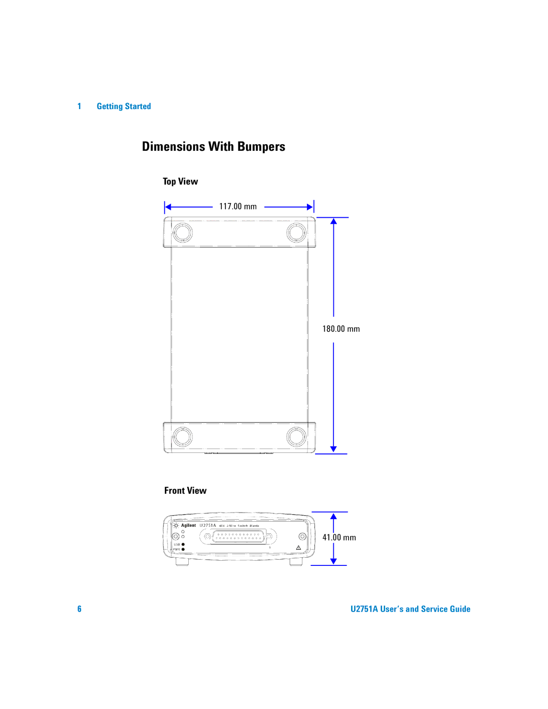
1 Getting Started
Dimensions With Bumpers
Top View
117.00 mm
180.00 mm
Front View
41.00 mm
6
U2751A User’s and Service Guide
Page 21
Page 23
Page 22
Image 22
Page 21
Page 23
Contents
User’s and Service Guide
U T I O N WA R N I N G
Safety Symbols
CAT
From occurring
Instrument and accessories. The cables or wires should be
Any other volatile liquid to clean the device
Device protection may be impaired
Environmental Conditions
U T I O N
Regulatory Markings
Affixed product label is as shown below
Product Category
For more information
This Guide…
Getting Started
U2751A User’s and Service Guide
Declaration of Conformity DoC
T E
Contents
Chassis Installation
List of Figures
U2922A pin configuration
Pin backplane connector pin configuration
Panel view of the Agilent Measurement Manager
XIV
List of Tables
Electrical and mechanical specifications update per
Part number and description of replaceable part
XVI
Chassis Installation
Installation
U2751A DSub Connector
Introduction
Introduction
Product Outlook
Product at a Glance
Bumpers
Pin backplane connector USB inlet
USB indicator Power indicator DSub connector
Power inlet
105.00 mm 175.00 mm
Product Dimensions
Dimensions Without Bumpers
25.00 mm
117.00 mm 180.00 mm
Dimensions With Bumpers
41.00 mm
Standard Purchase Items
Initial Inspection
Inspection and Maintenance
General Maintenance
Electrical Check
Installation
Installation and Configuration
With Agilent VEE Pro, LabVIEW, or Microsoft Visual Studio
Check Your System
Hard-disk space 1 GB
Install the IO Libraries Suite
Install the Module Driver
Install the Agilent Measurement Manager
T E
Connect the Module to Your PC
Proceeding
Getting Started
Select Ignore to disable the warning message
Go to Start Control Panel and double-clickSystem
Getting Started
T E
Send Commands To This Instrument
Verify Your Module Connection
IO Control will launch automatically when you start your PC
Launch Your Agilent Measurement Manager
Agilent Measurement Manager help file
U2751A DSub Connector
1Pin assignments
2U2922A pin configuration
U2922A Terminal Block
Female DSub connector Terminal block Retractable cover
3U2922A outlook
85.00 mm
85.00 mm 23.00 mm
90.00 mm 105.00 mm
105.00 mm 23.00 mm
Prior to attaching the U2922A to the U2751A
U2922A Terminal Block Installation
Cables
Housing
Jack screws of the U2922A
Pin Backplane Connector Pin Configuration
Description
Chassis Installation
Power Up Switch Control
Scpi Commands for System-Related Tasks
Power Up
Switch Control
1Switch matrix concept
Agilent Measurement Manager Operation
Scpi Commands
Relay Cycle Counter
3Panel view of the relay cycle counter
System-Related Operation
Error Conditions
Self-Test
Scpi Commands for System-Related Tasks
Example 4, Performing system-related tasks
Characteristics and Specifications
Product Characteristics
Operating Environment
Product Specifications
General characteristics
Service Information
Checking Defective Relays
Row Column
Replaceable Parts
2Part number and description of replaceable part
Disassembly Instructions
DIAGnosticRELayCYCLesCLEar @chlist
Reassembly Instructions
Contacting Agilent Technologies
Index
Index
Contact us
Top
Page
Image
Contents