Operation and Features | 2 |
Switch Control
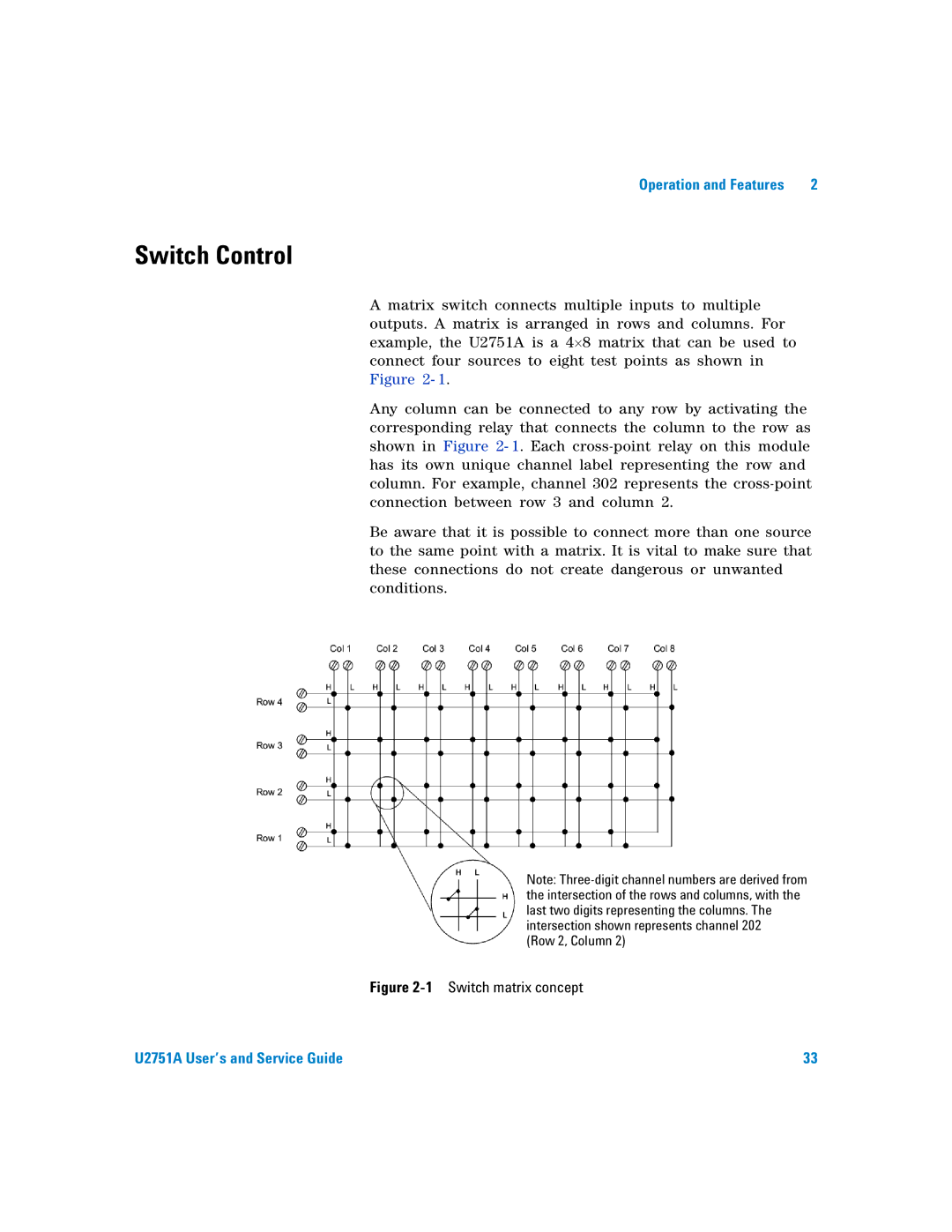
A matrix switch connects multiple inputs to multiple outputs. A matrix is arranged in rows and columns. For example, the U2751A is a 4×8 matrix that can be used to connect four sources to eight test points as shown in Figure 2- 1.
Any column can be connected to any row by activating the corresponding relay that connects the column to the row as shown in Figure 2- 1. Each
Be aware that it is possible to connect more than one source to the same point with a matrix. It is vital to make sure that these connections do not create dangerous or unwanted conditions.
Note:
(Row 2, Column 2)
Figure 2-1 Switch matrix concept
U2751A User’s and Service Guide | 33 |