WIRING DIAGRAM:
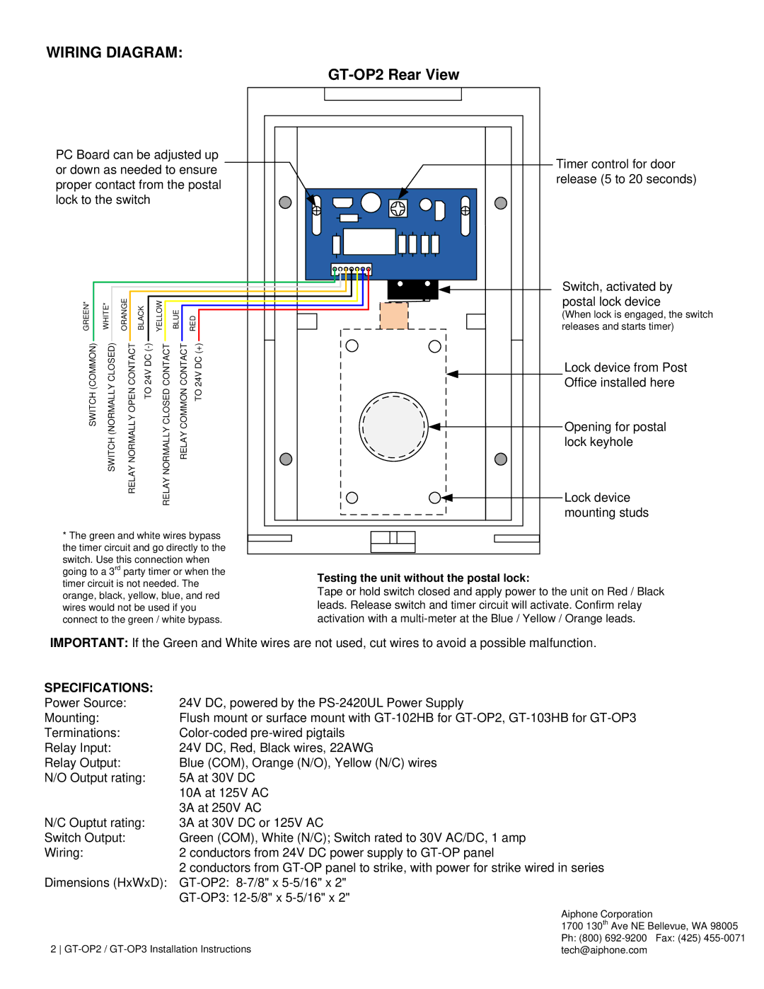
GT-OP2 Rear View
PC Board can be adjusted up or down as needed to ensure proper contact from the postal lock to the switch
GREEN* |
| WHITE* |
| ORANGE |
| BLACK |
| YELLOW |
|
| BLUE |
|
|
|
|
|
|
|
|
|
|
|
| ||||||
|
|
|
|
|
|
|
|
| ||||||
|
|
|
|
|
|
|
| |||||||
|
|
|
|
| RED |
| ||||||||
|
|
|
|
| ||||||||||
|
|
|
| |||||||||||
|
|
|
|
|
|
|
|
|
|
|
|
|
|
|
SWITCH (COMMON) | SWITCH (NORMALLY CLOSED) | RELAY NORMALLY OPEN CONTACT | TO 24V DC | RELAY NORMALLY CLOSED CONTACT | RELAY COMMON CONTACT | TO 24V DC (+) | ||||||||
*The green and white wires bypass the timer circuit and go directly to the switch. Use this connection when going to a 3rd party timer or when the timer circuit is not needed. The orange, black, yellow, blue, and red wires would not be used if you
connect to the green / white bypass.
Timer control for door release (5 to 20 seconds)
Switch, activated by postal lock device
(When lock is engaged, the switch releases and starts timer)
Lock device from Post
Office installed here
Opening for postal lock keyhole
Lock device mounting studs
Testing the unit without the postal lock:
Tape or hold switch closed and apply power to the unit on Red / Black leads. Release switch and timer circuit will activate. Confirm relay activation with a
IMPORTANT: If the Green and White wires are not used, cut wires to avoid a possible malfunction.
SPECIFICATIONS: |
|
Power Source: | 24V DC, powered by the |
Mounting: | Flush mount or surface mount with |
Terminations: | |
Relay Input: | 24V DC, Red, Black wires, 22AWG |
Relay Output: | Blue (COM), Orange (N/O), Yellow (N/C) wires |
N/O Output rating: | 5A at 30V DC |
| 10A at 125V AC |
| 3A at 250V AC |
N/C Ouptut rating: | 3A at 30V DC or 125V AC |
Switch Output: | Green (COM), White (N/C); Switch rated to 30V AC/DC, 1 amp |
Wiring: | 2 conductors from 24V DC power supply to |
| 2 conductors from |
Dimensions (HxWxD): | |
|
Aiphone Corporation
1700 130th Ave NE Bellevue, WA 98005
2 | Ph: (800) | Fax: (425) |
tech@aiphone.com |
|