Installation
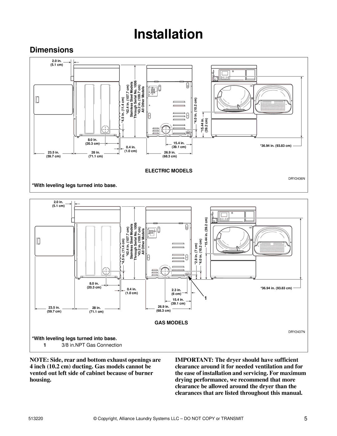
Dimensions
2.0 in.
(5.1 cm)
23.5in.
(59.7 cm)
8.0in.
(20.3 cm)
28in.
(71.1 cm)
*4.5 in. (11.4 cm) *42.4 in. (107.7 cm) Stainless Steel Models Through Serial No. 1006 *43.2 in. (109.7 cm) All Other Models | *4.0 in. (10.2 cm) | *15.44 in. (39.2 cm) | |
| 15.4 in. | *36.94 in. (93.83 cm) | |
0.4 in. | (39.1 cm) | ||
| |||
(1.0 cm) | 26.9 in. |
| |
| (68.3 cm) |
| |
| ELECTRIC MODELS | DRY2436N | |
|
| ||
|
| DRY2436N |
*With leveling legs turned into base.
2.0 in.
(5.1 cm)
23.5in.
(59.7 cm)
8.0 in. |
(20.3 cm) |
![]() 28 in.
28 in. ![]() (71.1 cm)
(71.1 cm)
*4.5 in. (11.4 cm) | *42.4 in. (107.7 cm) Stainless Steel Models Through Serial No. 1006 | *43.2 in. (109.7 cm) All Other Models | *2.8 in. (7 cm) | *4.0 in. (10.2 cm) | *15.44 in. (39.2 cm) |
|
|
|
|
|
|
| |
|
|
|
|
|
| *36.94 in. (93.83 cm) | |
0.4 in. |
| ||||||
| 2.3 in. |
| |||||
(1.0 cm) |
| (6 cm) |
|
|
|
|
|
| 1 |
| |||||
|
| 15.4 in. |
| ||||
26.9in. (39.1 cm)
![]() (68.3 cm)
(68.3 cm) ![]()
GAS MODELS
*With leveling legs turned into base.
13/8 in.NPT Gas Connection
DRY2437N
DRY2437N
NOTE: Side, rear and bottom exhaust openings are 4 inch (10.2 cm) ducting. Gas models cannot be vented out left side of cabinet because of burner housing.
IMPORTANT: The dryer should have sufficient clearance around it for needed ventilation and for the ease of installation and servicing. For maximum drying performance, we recommend that more clearance be allowed around the dryer than the clearances that are listed throughout this manual.
513220 | © Copyright, Alliance Laundry Systems LLC – DO NOT COPY or TRANSMIT | 5 |
