For Natural Gas: Check the gas input rate by observing the gas meter, when available, making sure all other gas appliances are turned off. The test hand on the meter should be timed for at least one revolution. Note the number of seconds for one revolution.
BTU/HR | = | Cubic Feet Per Revolution x 3600 x Heating | |
INPUT |
| # Seconds Per Revolution | Value |
The heating value of the gas can be obtained from the local utility company.
For Propane Gas: The only check for the gas input rate is to properly adjust the manifold pressure using a manometer. Typical manifold set point for installations at altitudes from 0 to 4500 feet above sea level is 10.0" W.C.
Temperature Rise
Check the temperature rise and, if necessary, adjust blower speed to maintain temperature rise within the range shown on the unit rating plate.
High Altitude
Ratings are shown on the rating plate for elevations up to 4500 feet. For elevations above 4500 feet, ratings should be reduced at a rate of 4% for each 1000 feet above sea level. See the National Fuel Gas Code Z223.1 (latest edition) or the Canadian Installation Codes
Secure Owner’s Approval
When the system is functioning properly, secure the owner’s approval. Show the owner the location of all disconnect switches and the thermostat. Instruct the owner on how to start and stop the unit and how to adjust temperature settings within the limitations of the system.
OPERATION
Cooling System
The cooling system is a complete factory package utilizing an
Unit compressors have internal protection. In the event there is an abnormal rise in the temperature of the compressor, the protector will open and cause the compressor to stop.
Cooling Sequence of Operation
When the thermostat calls for cooling, R is closed to G and Y (see the wiring diagrams beginning on page 15). This action completes the low voltage control circuit, energizing the compressor, condenser fan motor, and blower motor.
Blower Delay – Cooling
The circulating air blower is controlled by a timing circuit in the integrated blower/ignition control. Timings are not adjustable. Blower “on” delay is 5 seconds after the compressor starts and blower “off” timing is 90 seconds after the cooling system shuts down .
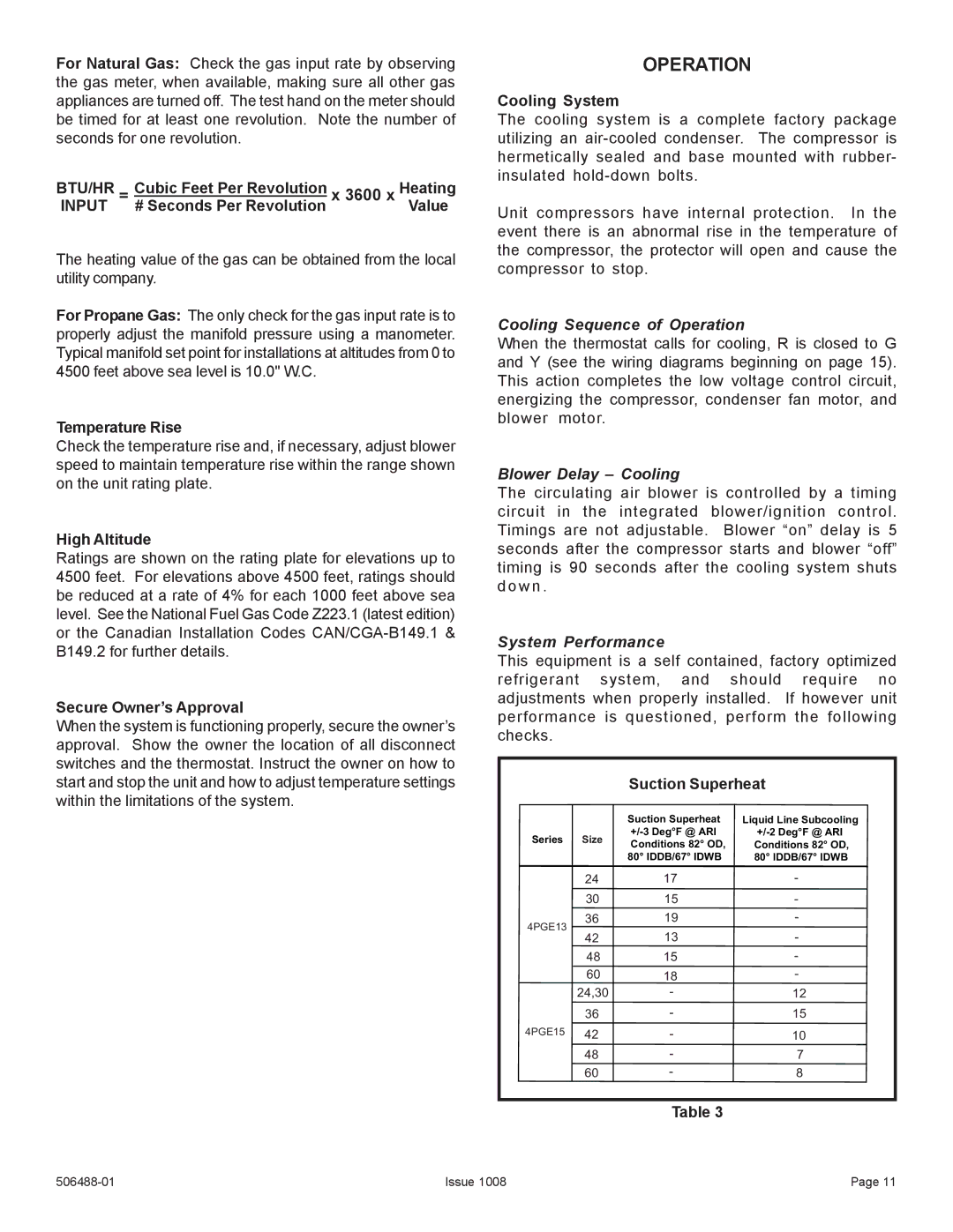
System Performance
This equipment is a self contained, factory optimized refrigerant system, and should require no adjustments when properly installed. If however unit performance is questioned, perform the following checks.
Suction Superheat
|
| Suction Superheat | Liquid Line Subcooling | |
Series | Size | |||
Conditions 82° OD, | Conditions 82° OD, | |||
|
| |||
|
| 80° IDDB/67° IDWB | 80° IDDB/67° IDWB | |
|
|
|
|
24 | 17 | - | |||
|
|
|
| ||
30 | 15 | - | |||
|
|
|
|
|
|
36 | 19 | - | |||
4PGE13 |
|
|
| ||
| 13 | - | |||
42 | |||||
|
|
|
| ||
48 | 15 | - | |||
|
|
|
| ||
60 | 18 | - | |||
24,30 | - | 12 | |||
|
|
|
|
| |
36 | - | 15 | |||
|
|
|
|
| |
4PGE15 42 | - | 10 | |||
| 48 | - | 7 | ||
|
|
|
|
| |
60 | - | 8 | |||
|
|
|
|
|
|
Table 3
Issue 1008 | Page 11 |