Minimum Required Surface Area
for Disposable Filters
Nominal Cooling | Filter Area | |
(sq. ft.) | ||
| ||
|
| |
24,000 | 2.67 | |
|
| |
30,000 | 3.33 | |
|
| |
36,000 | 4.00 | |
|
| |
42,000 | 4.67 | |
|
| |
48,000 | 5.33 | |
|
| |
60,000 | 6.67 | |
|
|
Table 2
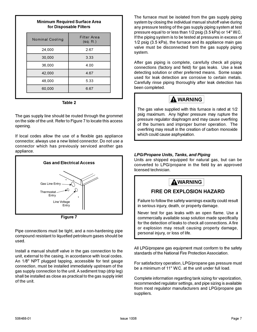
The gas supply line should be routed through the grommet on the side of the unit. Refer to Figure 7 to locate this access opening.
If local codes allow the use of a flexible gas appliance connector, always use a new listed connector. Do not use a connector which has previously serviced another gas appliance.
Gas and Electrical Access
Gas Line Entry ![]()
Thermostat ![]()
Entry
Line Voltage
Entry
Figure 7
Pipe connections must be tight, and a
Install a manual shutoff valve in the gas connection to the unit, external to the casing, in accordance with local codes. An 1/8" NPT plugged tapping, accessible for test gauge connection, must be installed immediately upstream of the gas supply connection to the unit. A sediment trap (drip leg) shall be installed as close as practical to the gas supply inlet of the unit.
The furnace must be isolated from the gas supply piping system by closing the individual manual shutoff valve during any pressure testing of the gas supply piping system at test pressure equal to or less than 1/2 psig (3.5 kPa) or 14" W.C. If the piping system is to be tested at pressures in excess of 1/2 psig (3.5 kPa), the furnace and its appliance main gas valve must be disconnected from the gas supply piping system.
After gas piping is complete, carefully check all piping connections (factory and field) for gas leaks. Use a leak detecting solution or other preferred means. Some soaps used for leak detection are corrosive to certain metals. Carefully rinse piping thoroughly after leak detection has been completed.
![]()
![]() WARNING
WARNING
The gas valve supplied with this furnace is rated at 1/2 psig maximum. Any higher pressure may rupture the pressure regulator diaphragm and may cause overfiring of the burners and improper burner operation. The overfiring may result in the creation of carbon monoxide which could cause asphyxiation.
LPG/Propane Units, Tanks, and Piping
Units are shipped equipped for natural gas, but can be converted to LPG/propane in the field by an approved licensed technician.
![]()
![]() WARNING
WARNING
FIRE OR EXPLOSION HAZARD
Failure to follow the safety warnings exactly could result in serious injury, death, or property damage.
Never test for gas leaks with an open flame. Use a commercially available soap solution made specifically for the detection of leaks to check all connections. A fire or explosion may result causing property damage, personal injury, or loss of life.
All LPG/propane gas equipment must conform to the safety standards of the National Fire Protection Association.
For satisfactory operation, LPG/propane gas pressure must be a minimum of 11" W.C. at the unit under full load.
Complete information regarding tank sizing for vaporization, recommended regulator settings, and pipe sizing is available from most regulator manufacturers and LPG/propane gas suppliers.
Issue 1008 | Page 7 |
