Insure unit is installed per manufacturer’s instructions and that line voltage and air flows are correct. Refer to Table 3 for proper superheat or subcooling values. Check superheat settings by measuring pressure at the suction line service port. For TXV systems, measure pressure at the liquid service port. Take line temperature within 2 inches of service port connection to its main tube. If unit superheat/subcooling varies by more than table allowance, check internal seals, service panels and duct work for air leaks, as well as restrictions and blower speed settings. If unit performance remains questionable, remove charge, evacuate to 500 Microns, and weigh in refrigerant to name plate charge. It is critical that the exact charge is
Heating System
With the proper thermostat and
Heating Sequence of Operation
1.When the thermostat calls for heat, the combustion blower is energized by the ignition control.
2.When the speed of the combustion blower reaches proper RPM, the pressure switch closes, initiating the
3.When
in the
4.The ignition control is designed to repeat this “trial for ignition” a total of three times. If, at the end of the third trial, a flame still has not been established, the ignition control will repeat the trial for ignition sequence 1 hour later. The
5.Thirty seconds (nominal) after the initial trial for ignition, the circulation air blower will start.
6.When the thermostat is satisfied, the combustion blower and gas valve are
Circulating Air Blower
Depending on the package unit model, the blower motor will be either a
PSC Motor
The circulating air blower is controlled by a timing circuit in the integrated blower/ignition control. Timings are not adjustable.
Cooling – Blower “on” delay is 5 seconds after call for cooling. Blower “off” delay is 90 seconds after the cooling system shuts down.
Heating – Blower “on” delay is 30 seconds nominal after burner ignition. Blower "off" delay is approximately 120 seconds after the thermostat is satisfied.
|
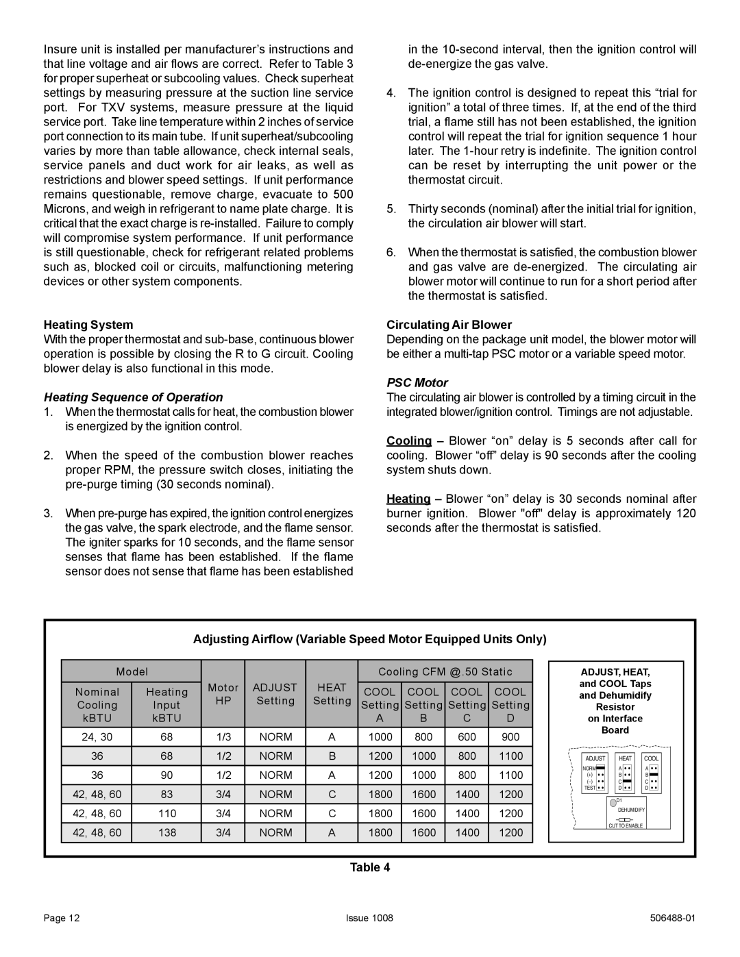
| Adjusting Airflow (Variable Speed Motor Equipped Units Only) |
|
|
| ||||||
Model |
|
|
| Cooling CFM @.50 Static | ADJUST, HEAT, | ||||||
Nominal | Heating | Motor | ADJUST | HEAT | COOL | COOL | COOL | COOL | and COOL Taps | ||
HP | Setting | Setting | and Dehumidify | ||||||||
Cooling | Input | Setting Setting Setting Setting | Resistor |
| |||||||
kBTU | kBTU |
|
|
| A | B | C | D | on Interface |
| |
24, 30 | 68 | 1/3 | NORM | A | 1000 | 800 | 600 | 900 | Board |
| |
|
|
| |||||||||
36 | 68 | 1/2 | NORM | B | 1200 | 1000 | 800 | 1100 | ADJUST | HEAT | COOL |
36 | 90 | 1/2 | NORM | A | 1200 | 1000 | 800 | 1100 | NORM | A | A |
(+) | B | B | |||||||||
|
|
|
|
|
|
|
|
| C | C | |
42, 48, 60 | 83 | 3/4 | NORM | C | 1800 | 1600 | 1400 | 1200 | TEST | D | D |
| D1 |
| |||||||||
42, 48, 60 | 110 | 3/4 | NORM | C | 1800 | 1600 | 1400 | 1200 |
|
| |
| DEHUMIDIFY | ||||||||||
42, 48, 60 | 138 | 3/4 | NORM | A | 1800 | 1600 | 1400 | 1200 |
| CUT TO ENABLE |
|
|
|
| |||||||||
Table 4
Page 12 | Issue 1008 |