WARNING

Improper installation of the furnace can result in personal injury or death. Combustion and flue products must never be allowed to enter the return air system or air in the living space. Use sheet metal screws and joint tape to seal return air system to furnace.

In platform installations with furnace return, the furnace should be sealed airtight to the return air plenum. A door must never be used as a portion of the return air duct system. The base must provide a stable support and an airtight seal to the furnace. Allow absolutely no sagging, cracks, gaps, etc.

For no reason should return and supply air duct systems ever be connected to or from other heating devices such as a fireplace or stove, etc. Fire, explosion, carbon monoxide poisoning, personal injury and/or property damage could result.

The unit may be installed three ways in downflow applica- tions: on non-combustible flooring, on combustible flooring using an additive base, or on a reverse-flow cooling coil cabinet. Do not drag the unit across the floor in the downflow position. Floor and furnace flange damage will result.

Refer to Figure 11 for clearances in downflow applica- tions.

Downflow Application Installation Clearances

Top

Left Side

Right Side


Bottom


Top


0


*Front


0


Back


0


Sides


0†


Vent


0


Floor


NC ‡


*Front clearance in alcove installation must be 24 in. (610 mm). Maintain a minimum of 24 in. (610 mm) for front service access. †Allow proper clearances to accommodate condensate trap.

‡The furnace may be installed on a combustible wood floor if an optional additive base is installed between the furnace and the combustible floor.

FIGURE 11

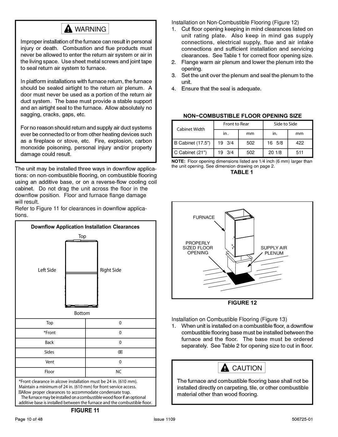
Installation on Non-Combustible Flooring (Figure 12)

1.Cut floor opening keeping in mind clearances listed on unit rating plate. Also keep in mind gas supply connections, electrical supply, flue and air intake connections and sufficient installation and servicing clearances. See Table 1 for correct floor opening size.

2.Flange warm air plenum and lower the plenum into the opening.

3.Set the unit over the plenum and seal the plenum to the unit.

4.Ensure that the seal is adequate.

NON−COMBUSTIBLE FLOOR OPENING SIZE

Cabinet Width

Front to Rear

Side to Side


in .

mm

in.

mm


B Cabinet (17.5")

19 − 3/4

502

16 − 5/8

422


C Cabinet (21")

19 − 3/4

502

20−1/8

511


NOTE: Floor opening dimensions listed are 1/4 inch (6 mm) larger than the unit opening. See dimension drawing on page 2.

TABLE 1

FURNACE

PROPERLY


SIZED FLOOR

SUPPLY AIR

OPENING

PLENUM

FIGURE 12

Installation on Combustible Flooring (Figure 13)

1.When unit is installed on a combustible floor, a downflow combustible flooring base must be installed between the furnace and the floor. The base must be ordered separately. See Table 2 for opening size to cut in floor.

CAUTION

The furnace and combustible flooring base shall not be installed directly on carpeting, tile, or other combustible material other than wood flooring.

Page 10 of 48

Issue 1109

506725-01

Page 10
Image 10
Allied Air Enterprises A93DF, A95DF Installation on Non-Combustible Flooring Figure, NON−COMBUSTIBLE Floor Opening Size

A95DF, 95G1DF, A93DF, 92G1DF specifications

Allied Air Enterprises offers a range of high-efficiency commercial and residential heating and cooling systems, with models like the 92G1DF, A93DF, 95G1DF, and A95DF gaining popularity for their cutting-edge technology and advanced features. Each of these models stands out in performance, reliability, and energy efficiency, making them excellent choices for diverse applications.

The 92G1DF model features a multi-stage gas valve that enhances temperature regulation, allowing for more precise heating. With an impressive Annual Fuel Utilization Efficiency (AFUE) rating, this furnace efficiently utilizes fuel, resulting in lower energy costs and reduced emissions. Its compact design makes it suitable for installations in tight spaces, while the durable heat exchanger extends the unit’s lifespan.

In contrast, the A93DF is engineered for enhanced comfort and flexibility. This model incorporates a variable-speed blower motor, which adjusts air circulation according to the heating demands in the space. This feature not only maximizes comfort by providing consistent temperatures but also promotes energy savings by reducing unnecessary power consumption. Additionally, the A93DF includes advanced diagnostic capabilities that simplify troubleshooting and maintenance, making it a favorite among HVAC professionals.

The 95G1DF is another noteworthy model that combines versatile performance with exceptional efficiency. This furnace boasts an AFUE rating of up to 95%, making it one of the most efficient models in its class. Its innovative design includes a secondary heat exchanger that captures additional heat from exhaust gases, optimizing energy utilization. Furthermore, the 95G1DF is equipped with an advanced control system that allows homeowners to set specific comfort levels.

Lastly, the A95DF model takes efficiency to a new level. With features such as a modulating gas valve and a variable-speed blower, this unit seamlessly adapts to changing heating needs. The A95DF not only heats a space but also enhances air quality through advanced filtration options. Its whisper-quiet operation adds to user satisfaction, making it ideal for residential settings.

In summary, Allied Air Enterprises' models 92G1DF, A93DF, 95G1DF, and A95DF demonstrate a commitment to innovation and energy efficiency, with features designed to provide superior comfort and reliability. With their advanced technologies and high-performance characteristics, these models are positioned as top contenders in the heating and cooling marketplace, ensuring that customers can enjoy a comfortable environment year-round.