ATFS705EFCSC60 specifications
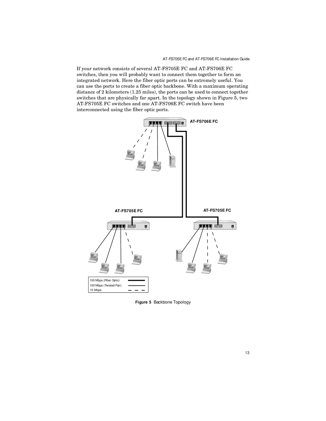
The Allied Telesis ATFS705EFCSC60 is a robust and feature-rich network switch designed for small to medium-sized enterprises. Combining advanced networking technologies with versatility, this switch caters to the increasing demands for efficient and reliable network performance.One of the main features of the ATFS705EFCSC60 is its support for Ethernet networking with a variety of port configurations. This switch features five 10/100/1000 Mbps Ethernet ports, providing high-speed data transmission capabilities. The inclusion of a gigabit capability ensures that network bottlenecks are minimized, enabling smooth data flow between connected devices, making it ideal for bandwidth-intensive applications such as video conferencing and large file transfers.
Moreover, the ATFS705EFCSC60 excels in Layer 2 switching capabilities. It supports vital functionalities like VLAN (Virtual Local Area Network) support, allowing network administrators to segment their network into different logical sections. This segmentation enhances security, reduces broadcast domains, and improves overall network performance. The switch also supports Spanning Tree Protocol (STP) and Rapid Spanning Tree Protocol (RSTP) to prevent loops within the network topology, ensuring reliable redundancy.
Another standout feature of the ATFS705EFCSC60 is its advanced management capabilities. It provides web-based management interfaces, which facilitate easy configuration and monitoring of the network switch. Network administrators can also utilize SNMP (Simple Network Management Protocol) for remote monitoring, allowing for real-time insights into the performance and health of the switch.
Power over Ethernet (PoE) support is another significant advantage of this switch. It allows the switch to deliver power to connected devices such as IP cameras, VoIP phones, and wireless access points through the Ethernet cable, eliminating the need for additional power sources. This feature simplifies installation and reduces clutter, making it an excellent choice for environments where power outlets are limited.
In terms of build and design, the ATFS705EFCSC60 is designed for reliability and durability. It features a robust chassis that can withstand various environmental conditions, making it suitable for different deployment scenarios. The switch’s fanless design also ensures silent operation, making it ideal for office environments.
In summary, the Allied Telesis ATFS705EFCSC60 is a high-performance network switch that blends performance, reliability, and advanced features. Its support for gigabit Ethernet, VLAN configuration, PoE capabilities, and comprehensive management options make it an excellent choice for businesses looking to enhance their network infrastructure. Whether used in a growing enterprise or as part of a point solution, the ATFS705EFCSC60 presents itself as a valuable asset in modern networking.

