6 | Rapier Switch |
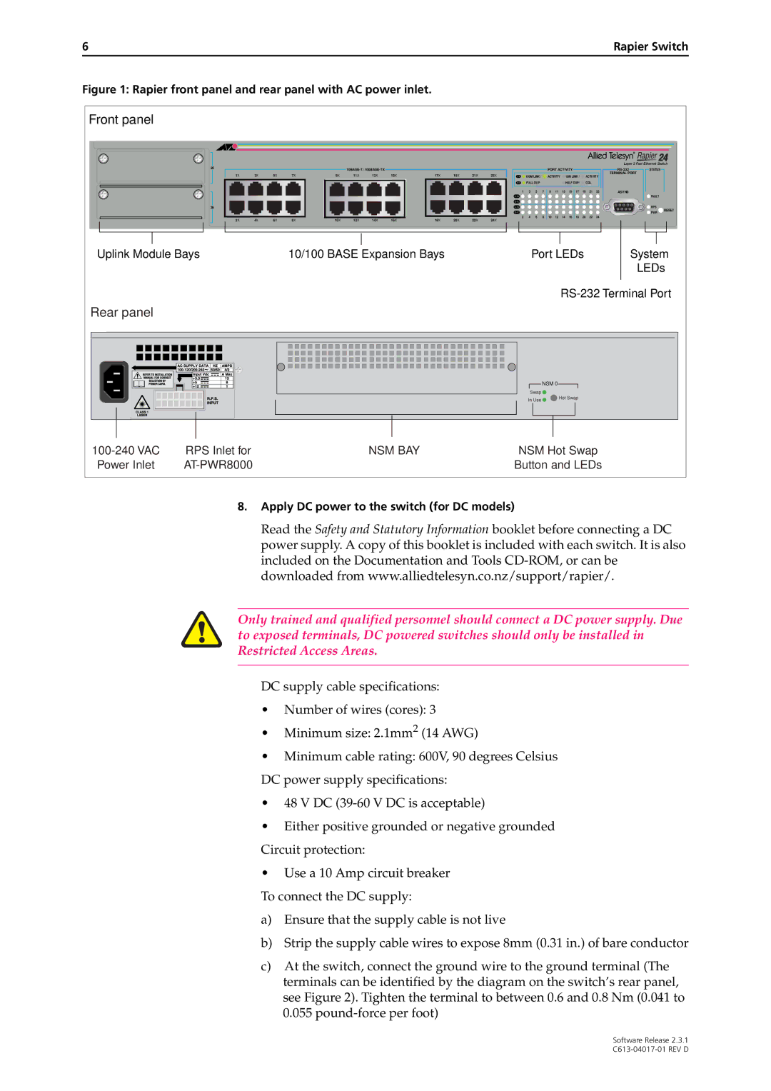
Figure 1: Rapier front panel and rear panel with AC power inlet.
Front panel |
|
|
|
|
|
|
|
|
|
|
|
|
|
|
|
|
|
|
|
|
|
|
|
|
|
|
|
|
|
|
|
|
|
|
|
|
|
|
|
|
|
|
|
|
|
|
|
|
|
|
| Layer 3 Fast Ethernet Switch | |
| 25 |
|
|
|
|
|
|
|
|
|
|
|
|
| PORT ACTIVITY |
|
|
|
| STATUS | ||||||
| 1X | 3X | 5X | 7X | 9X | 11X | 13X | 15X | 17X | 19X | 21X | 23X |
| 100M LINK / |
| ACTIVITY |
| 10M LINK / |
| ACTIVITY | TERMINAL PORT | |||||
| L /A |
|
|
|
|
| ||||||||||||||||||||
|
|
|
|
|
|
|
|
|
|
|
|
| D/C | FULL DUP |
|
|
|
| HALF DUP/ |
| COL |
|
|
| ||
|
|
|
|
|
|
|
|
|
|
|
|
| 1 | 3 | 5 | 7 | 9 | 11 | 13 | 15 | 17 | 19 | 21 | 23 | ASYN0 |
|
|
|
|
|
|
|
|
|
|
|
|
|
| L /A |
|
|
|
|
|
|
|
|
|
|
|
| FAULT |
|
|
|
|
|
|
|
|
|
|
|
|
| D/C |
|
|
|
|
|
|
|
|
|
|
|
|
|
| 26 |
|
|
|
|
|
|
|
|
|
|
| L /A |
|
|
|
|
|
|
|
|
|
|
|
| RPS |
|
|
|
|
|
|
|
|
|
|
|
|
| D/C |
|
|
|
|
|
|
|
|
|
|
|
| RESET |
|
|
|
|
|
|
|
|
|
|
|
|
|
|
|
|
|
|
|
|
|
|
|
|
| PWR | |
| 2X | 4X | 6X | 8X | 10X 12X 14X 16X | 18X | 20X | 22X | 24X | 2 | 4 | 6 | 8 | 10 | 12 | 14 | 16 | 18 | 20 | 22 | 24 |
|
| |||
|
|
|
|
|
|
|
|
|
|
|
|
|
|
| ||||||||||||
Uplink Module Bays |
|
| 10/100 BASE Expansion Bays |
|
|
|
|
| Port LEDs |
|
|
| System | |||||||||||||
|
|
|
|
|
|
|
|
|
|
|
|
|
|
|
|
|
|
|
|
|
|
|
|
|
| LEDs |
|
|
|
|
|
|
|
|
|
|
|
|
|
|
|
|
|
|
| ||||||||
Rear panel |
|
|
|
|
|
|
|
|
|
|
|
|
|
|
|
|
|
|
|
|
|
|
|
|
|
|
|
|
|
|
|
|
|
|
|
|
|
|
|
|
|
| NSM 0 |
|
|
|
|
|
|
|
| ||
|
|
|
|
|
|
|
|
|
|
|
|
|
| Swap |
|
|
|
|
|
|
|
|
|
|
| |
|
|
|
|
|
|
|
|
|
|
|
|
|
| In Use |
|
| Hot Swap |
|
|
|
|
| ||||
|
|
|
|
|
|
|
|
|
|
|
|
|
|
|
|
|
|
|
|
|
|
|
|
| ||
RPS Inlet for |
|
|
|
|
| NSM BAY |
|
|
|
| NSM Hot Swap |
|
| |||||||||||||
Power Inlet |
|
|
|
|
|
|
|
|
|
|
| Button and LEDs |
|
| ||||||||||||
8.Apply DC power to the switch (for DC models)
Read the Safety and Statutory Information booklet before connecting a DC power supply. A copy of this booklet is included with each switch. It is also included on the Documentation and Tools
Only trained and qualified personnel should connect a DC power supply. Due to exposed terminals, DC powered switches should only be installed in Restricted Access Areas.
DC supply cable specifications:
•Number of wires (cores): 3
•Minimum size: 2.1mm2 (14 AWG)
•Minimum cable rating: 600V, 90 degrees Celsius DC power supply specifications:
•48 V DC
•Either positive grounded or negative grounded Circuit protection:
•Use a 10 Amp circuit breaker
To connect the DC supply:
a)Ensure that the supply cable is not live
b)Strip the supply cable wires to expose 8mm (0.31 in.) of bare conductor
c)At the switch, connect the ground wire to the ground terminal (The terminals can be identified by the diagram on the switch’s rear panel, see Figure 2). Tighten the terminal to between 0.6 and 0.8 Nm (0.041 to 0.055
Software Release 2.3.1