Quick Install Guide | 7 |
d)At the switch, connect the positive feed to the + (positive) terminal and the negative feed to the - (negative) terminal. Tighten the terminals to between 0.6 and 0.8 Nm (0.041 to 0.055
e)Ensure that there are no exposed conductor strands
f)Secure the supply cable (to the rack framework or similar object) so that the connections are isolated from any forces applied to the cable
g)Ensure that the circuit breaker is in the Off position
h)Connect the
i)Energise the circuit breaker
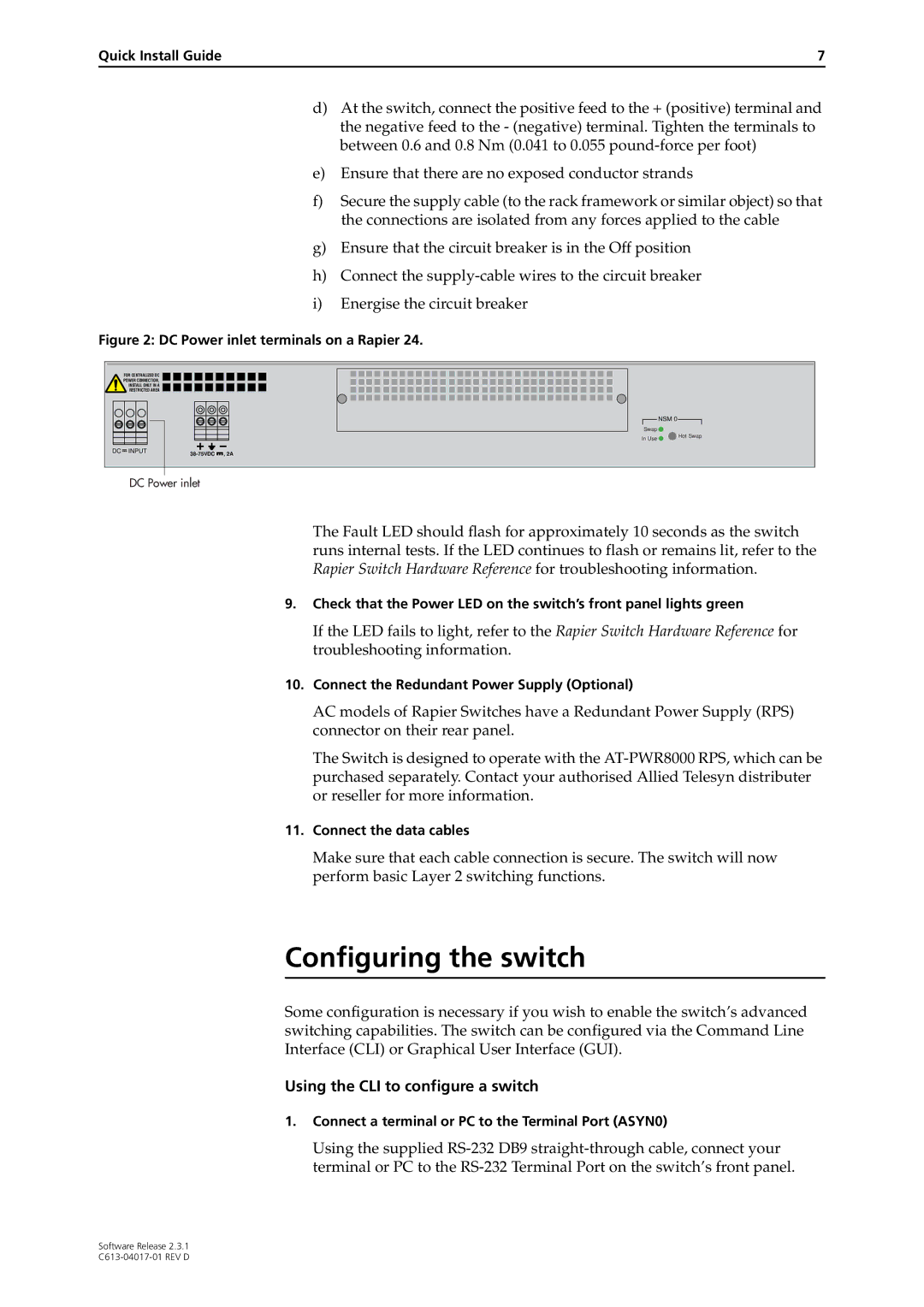
Figure 2: DC Power inlet terminals on a Rapier 24.
FOR CENTRALIZED DC
POWER CONNECTION,
INSTALL ONLY IN A
RESTRICTED AREA
DC INPUT |
![]() NSM 0
NSM 0![]()
Swap ![]()
In Use ![]() Hot Swap
Hot Swap
DC Power inlet
The Fault LED should flash for approximately 10 seconds as the switch runs internal tests. If the LED continues to flash or remains lit, refer to the Rapier Switch Hardware Reference for troubleshooting information.
9.Check that the Power LED on the switch’s front panel lights green
If the LED fails to light, refer to the Rapier Switch Hardware Reference for troubleshooting information.
10.Connect the Redundant Power Supply (Optional)
AC models of Rapier Switches have a Redundant Power Supply (RPS) connector on their rear panel.
The Switch is designed to operate with the
11.Connect the data cables
Make sure that each cable connection is secure. The switch will now perform basic Layer 2 switching functions.
Configuring the switch
Some configuration is necessary if you wish to enable the switch’s advanced switching capabilities. The switch can be configured via the Command Line Interface (CLI) or Graphical User Interface (GUI).
Using the CLI to configure a switch
1.Connect a terminal or PC to the Terminal Port (ASYN0)
Using the supplied
Software Release 2.3.1