HARDWARE INSTALATION
LED Indicator
PWR/Power
This indicator lights green when the Access Point receives power. Otherwise, it will be off.
LAN (Link/ACT)
The LED lights green when the LAN port is connected to a 100Mbps Ethernet station, the indicator blinks green while transmitting or receiving data .
WLAN (Link)
The indicator blinks green while the wireless AP is broadcasting packets.
Rear Panel
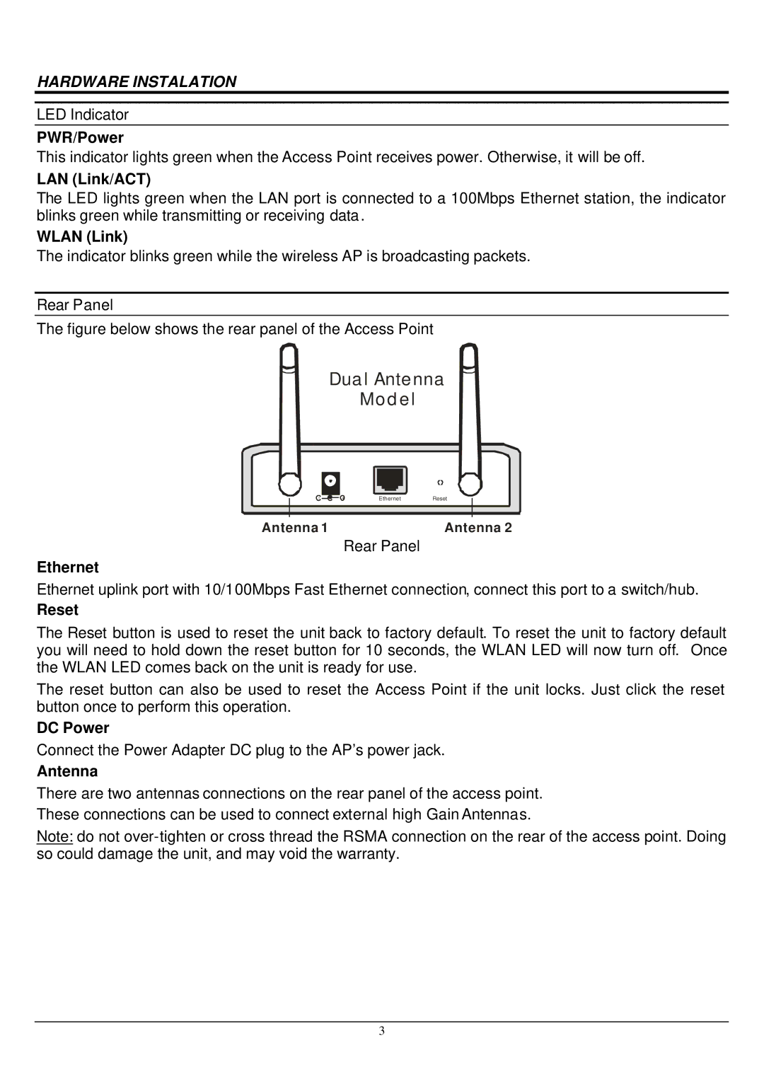
The figure below shows the rear panel of the Access Point
Dual Antenna
Model
-
+ | Ethernet | Reset |
Antenna 1 | Antenna 2 |
Rear Panel
Ethernet
Ethernet uplink port with 10/100Mbps Fast Ethernet connection, connect this port to a switch/hub.
Reset
The Reset button is used to reset the unit back to factory default. To reset the unit to factory default you will need to hold down the reset button for 10 seconds, the WLAN LED will now turn off. Once the WLAN LED comes back on the unit is ready for use.
The reset button can also be used to reset the Access Point if the unit locks. Just click the reset button once to perform this operation.
DC Power
Connect the Power Adapter DC plug to the AP’s power jack.
Antenna
There are two antennas connections on the rear panel of the access point. These connections can be used to connect external high Gain Antennas.
Note: do not
3
