Operating Manual
4. FRONT PANEL CONTROLS
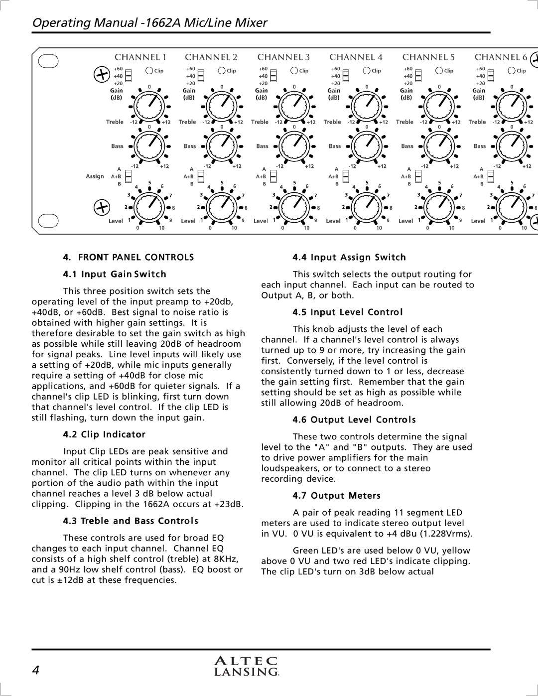
4.1 Input Gain Switch
This three position switch sets the operating level of the input preamp to +20db, +40dB, or +60dB. Best signal to noise ratio is obtained with higher gain settings. It is therefore desirable to set the gain switch as high as possible while still leaving 20dB of headroom for signal peaks. Line level inputs will likely use a setting of +20dB, while mic inputs generally require a setting of +40dB for close mic applications, and +60dB for quieter signals. If a channel's clip LED is blinking, first turn down that channel's level control. If the clip LED is still flashing, turn down the input gain.
4.2 Clip Indicator
Input Clip LEDs are peak sensitive and monitor all critical points within the input channel. The clip LED turns on whenever any portion of the audio path within the input channel reaches a level 3 dB below actual clipping. Clipping in the 1662A occurs at +23dB.
4.3 Treble and Bass Controls
These controls are used for broad EQ changes to each input channel. Channel EQ consists of a high shelf control (treble) at 8KHz, and a 90Hz low shelf control (bass). EQ boost or cut is ±12dB at these frequencies.
4.4 Input Assign Switch
This switch selects the output routing for each input channel. Each input can be routed to Output A, B, or both.
4.5 Input Level Control
This knob adjusts the level of each channel. If a channel's level control is always turned up to 9 or more, try increasing the gain first. Conversely, if the level control is consistently turned down to 1 or less, decrease the gain setting first. Remember that the gain setting should be set as high as possible while still allowing 20dB of headroom.
4.6 Output Level Controls
These two controls determine the signal level to the "A" and "B" outputs. They are used to drive power amplifiers for the main loudspeakers, or to connect to a stereo recording device.
4.7 Output Meters
A pair of peak reading 11 segment LED meters are used to indicate stereo output level in VU. 0 VU is equivalent to +4 dBu (1.228Vrms).
Green LED's are used below 0 VU, yellow above 0 VU and two red LED's indicate clipping. The clip LED's turn on 3dB below actual
4
