SWITCHERS

STEP:

This feature allows cycling through the inputs one at a time. It is used to select the next input from an ALL OFF condition. If this button is pressed once it switches to the next input in an increasing order. For example, if INPUT 3 is currently selected, pressing STEP SELECT once will switch to INPUT 4. If pressed again INPUT 5 is selected. If INPUT 6 is already selected, and the STEP SELECT button is pressed once, none of the inputs will be selected. This condition is similar to the ALL ON function. By pressing once more from the ALL OFF stage, INPUT 1 will be selected.

7.1.3OUTPUT CONTROL SECTION DELAY:

This function enables Sync Delay Switching in RGBHV and RGBS signals. Sync Delay allows the ”glitch” that normally takes place when switching between high-resolution sources to take place off screen. When the Sync Delay feature is enabled, the video portion of the image (RGB signals) is disconnected before the sync portion (H&V SYNC or CSYNC). When connecting the input, the video portion of the signal (RGB) is restored shortly after the incoming sync portion of the signal is connected. This delay time is factory pre-set to

2.5seconds. By pressing this button once, the SYNC DELAY feature is enabled and confirmed through the LED on top of the button. If it is pressed once more this feature is disabled and the LED turns off.

VIDEO OFF:

This feature allows a user to disable only the video (RGB channels) portion of the selected source. The sync portion (H&V, SYNC or CSYNC) of the selected source will continue to be sent to the display. This feature can be very helpful when the user does not want the display to go into a ”no display” or “no signal” mode (e.g. some data monitors will display a blue screen if no signal is present). To disable the video portion of the selected input, press the video off button once, the LED on the top

7

button should light up. To enable the video portion, press the button again and the LED will be in an OFF position. This feature is designed to work only with RGBHV, RGBS and RGsB format signals. It is similar to the ALL OFF mode except that there is only sync signal sent to the output for display.

7.2 RS-232 CONTROL

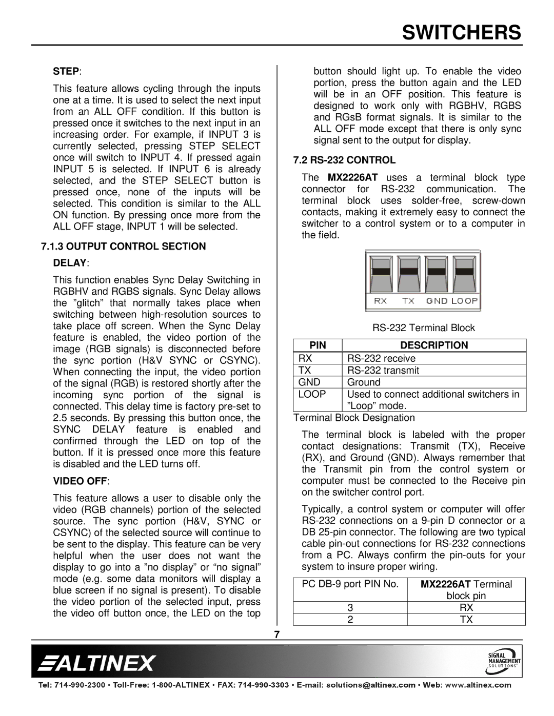
The MX2226AT uses a terminal block type connector for RS-232 communication. The terminal block uses solder-free, screw-down contacts, making it extremely easy to connect the switcher to a control system or to a computer in the field.


RS-232 Terminal Block


PIN

DESCRIPTION

RX

RS-232 receive

TX

RS-232 transmit

GND

Ground

LOOP

Used to connect additional switchers in


”Loop” mode.

Terminal Block Designation

The terminal block is labeled with the proper contact designations: Transmit (TX), Receive (RX), and Ground (GND). Always remember that the Transmit pin from the control system or computer must be connected to the Receive pin on the switcher control port.

Typically, a control system or computer will offer RS-232 connections on a 9-pin D connector or a DB 25-pin connector. The following are two typical cable pin-out connections for RS-232 connections from a PC. Always confirm the pin-outs for your system to insure proper wiring.

PC DB-9 port PIN No.

MX2226AT Terminal


block pin

3

RX

2

TX

7

Page 8
Image 8
Altinex MX2226AT manual Step, Output Control Section Delay, Video OFF, PIN Description

MX2226AT specifications

The Altinex MX2226AT is a sophisticated audio-visual switcher designed to meet the demands of professional audio-visual environments. It serves as an essential component for managing multiple video sources, allowing users to easily switch between devices for seamless presentations and conferences.

One of the standout features of the MX2226AT is its capability to handle up to six inputs and two outputs. This flexibility enables users to connect a variety of sources, including computers, projectors, and displays, ensuring comprehensive connectivity for any setup. The switcher supports multiple video formats, including VGA, Composite, S-Video, and Component, making it highly versatile for different audio-visual equipment.

The MX2226AT is equipped with advanced switching technology. The device utilizes a sophisticated matrix switching system that allows for not only straightforward input-output routing but also provides the ability to send any input to any output. This feature is particularly beneficial in complex setups where different video signals are needed at various output locations.

Another notable aspect of the MX2226AT is its user-friendly interface. The front panel features intuitive buttons for quick access to input selection, along with LED indicators that provide real-time feedback on the active inputs and outputs. Additionally, the switcher offers remote control capabilities, giving users the option to manage their media sources from a distance, which is ideal for dynamic presentations.

In terms of compatibility, the MX2226AT employs both analog and digital technologies, allowing integration with a wide range of devices. The switcher also includes integrated scaling functionality, ensuring that video resolutions are appropriately adjusted for optimal display quality, regardless of the original resolution of the source.

Built with reliability in mind, the MX2226AT features robust construction suitable for installation in a variety of environments, from boardrooms to lecture halls. Its durable design helps to maintain consistent performance during prolonged usage, ensuring that users can depend on the unit for critical presentations.

In summary, the Altinex MX2226AT is a powerful and versatile audio-visual switcher, ideal for environments requiring efficient management of multiple video sources. Its advanced features, user-friendly interface, and compatibility with various formats make it a valuable asset for professionals seeking to enhance their audio-visual setups.