SWITCHERS
7.3 RS-232 CONTROL
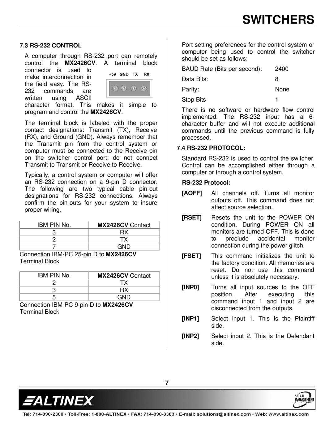
A computer through
make interconnection in the field easy. The RS-
232 commands are written using ASCII
character format. This makes it simple to program and control the MX2426CV.
The terminal block is labeled with the proper contact designations: Transmit (TX), Receive (RX), and Ground (GND). Always remember that the Transmit pin from the control system or computer must be connected to the Receive pin on the switcher control port; do not connect Transmit to Transmit or Receive to Receive.
Typically, a control system or computer will offer an
IBM PIN No. | MX2426CV Contact |
3 | RX |
2 | TX |
7 | GND |
Connection | |
Terminal Block |
|
|
|
IBM PIN No. | MX2426CV Contact |
2 | TX |
3 | RX |
5 | GND |
Connection
Port setting preferences for the control system or computer being used to control the switcher should be set as follows:
BAUD Rate (Bits per second): | 2400 |
Data Bits: | 8 |
Parity: | None |
Stop Bits | 1 |
There is no software or hardware flow control implemented. The
7.4 RS-232 PROTOCOL:
Standard
[AOFF] All channels off. Turns all monitor outputs off. This command does not affect source selection.
[RSET] Resets the unit to the POWER ON condition. During POWER ON all monitors are turned OFF. This is done to preclude accidental monitor connection during the power glitch.
[FSET] This command initializes the unit to the factory condition. All memories are reset. Do not use this command unless it is absolutely necessary.
[INP0] Turns all input sources to the OFF position. After executing this command input 1 and input 2 are disconnected from the outputs.
[INP1] Select input 1. This is the Plaintiff side.
[INP2] Select input 2. This is the Defendant side.
7