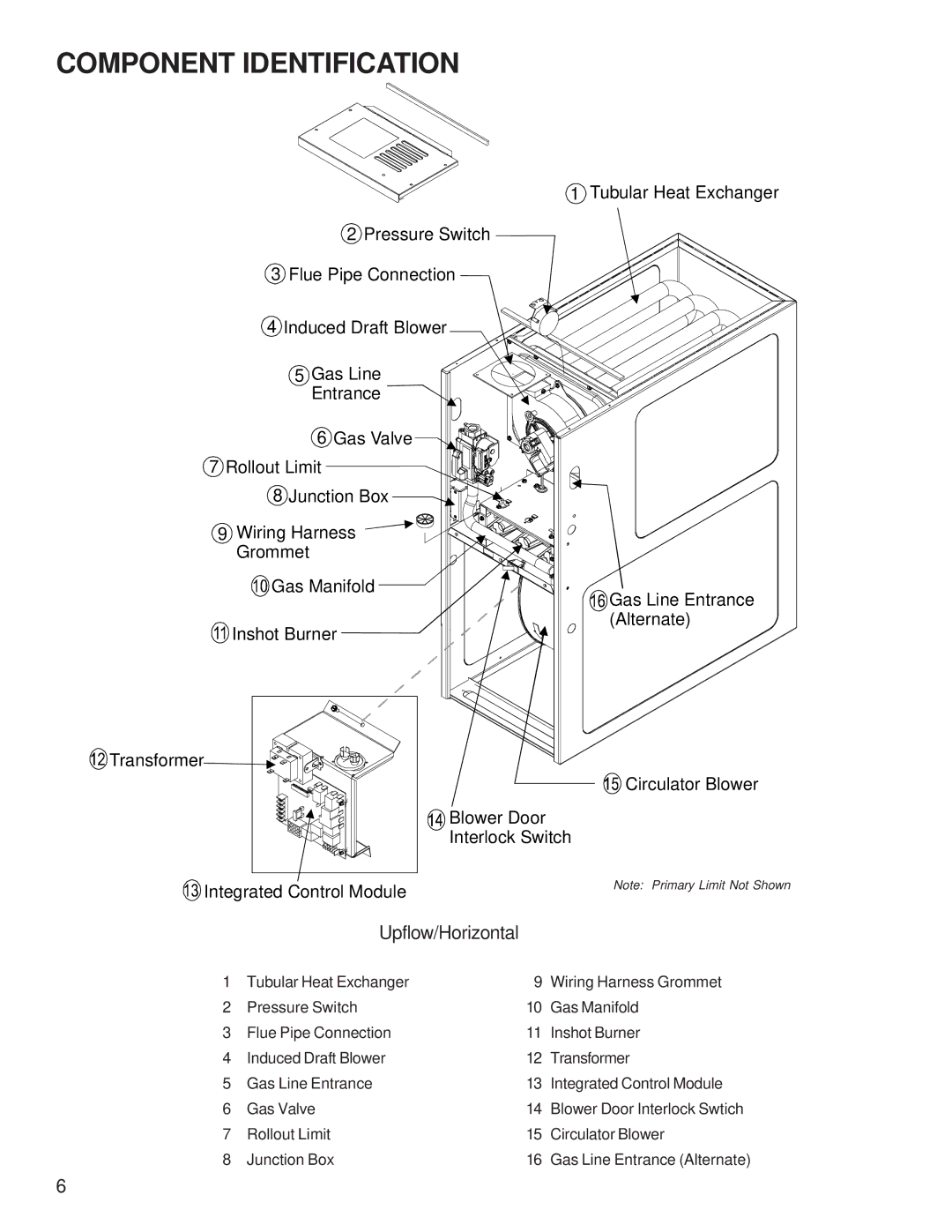
AMH* specifications
The Amana AMH* series is a line of advanced air conditioning and heating systems designed to provide efficient climate control for residential spaces. Renowned for their innovative features and technology, these systems prioritize comfort, sustainability, and ease of use.One of the standout features of the Amana AMH* series is its impressive energy efficiency. The units are equipped with high SEER (Seasonal Energy Efficiency Ratio) ratings, which indicate their ability to provide effective cooling while consuming less energy. This not only helps homeowners save on utility bills but also reduces their environmental impact, making the AMH* series an eco-friendly choice for climate control.
The Amana AMH* series incorporates state-of-the-art inverter technology. This technology allows the system to adjust its cooling or heating output based on the specific demands of the home at any given moment. Instead of operating at a single, fixed speed, the inverter-driven compressor can modulate its output, providing a more consistent temperature and improving overall comfort.
Additionally, these systems feature advanced refrigerant technology. They often utilize R-410A refrigerant, which is known for being more environmentally friendly compared to older refrigerants. This contributes to the overall efficiency of the units while minimizing harmful emissions, complying with modern environmental regulations.
Another notable characteristic of the Amana AMH* series is its noise level. Designed with sound insulation and advanced engineering, these units operate quietly, ensuring that the comfort of the indoor environment is not disrupted by excessive noise. This is particularly beneficial in residential settings where quiet operation is essential.
The user-friendly controls of the Amana AMH* systems make them easy to operate. Many units come with smart technology that allows homeowners to control their HVAC system remotely via smartphones or tablets. This feature not only enhances convenience but also allows for better management of energy consumption, further promoting efficiency.
Moreover, Amana products are known for their durability and reliability. Backed by a robust warranty, these systems are built with high-quality materials and components, ensuring they can withstand the test of time and varying weather conditions.
In conclusion, the Amana AMH* series represents a blend of energy efficiency, innovative technology, and user-friendly features, making it an excellent choice for homeowners seeking reliable and effective climate control solutions. With a focus on sustainability, comfort, and quiet operation, the AMH* series stands out as a leader in the HVAC market.

