Installing 4-Wire Power Cord
!WARNING
To avoid the risk of severe electrical shock or death, ground wire must be attached to frame of range, using ground screw provided. Ground wire must not contact any other terminal.
1.Remove rear wire cover on back of range.
2.Place strain relief (winged clamp) in cord access hole below terminal block.
•Strain relief is supplied with cord. Place wings through hole entering from bottom.
•Screw holes in clamp should be below mounting panel.
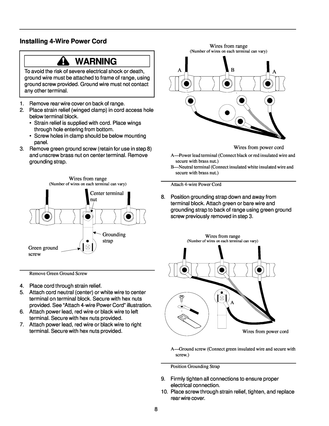
3.Remove green ground screw (retain for use in step 8) and unscrew brass nut on center terminal. Remove grounding strap.
Wires from range
(Number of wires on each terminal can vary)
Center terminal nut
![]() Grounding
Grounding
strap
Green ground screw
Remove Green Ground Screw
4.Place cord through strain relief.
5.Attach cord neutral (center) or white wire to center terminal on terminal block. Secure with hex nuts provided. See “Attach
6.Attach power lead, red wire or black wire to left terminal. Secure with hex nuts provided.
7.Attach power lead, red wire or black wire to right terminal. Secure with hex nuts provided.
Wires from range
(Number of wires on each terminal can vary)
| A |
|
|
| B |
|
|
| A | |||||
|
|
|
|
|
|
|
|
|
|
|
| |||
|
|
|
|
|
|
|
|
|
|
|
|
|
|
|
|
|
|
|
|
|
|
|
|
|
|
|
|
|
|
|
|
|
|
|
|
|
|
|
|
|
|
|
|
|
Wires from power cord
Attach
8.Position grounding strap down and away from terminal block. Attach green or bare wire and grounding strap to back of range using green ground screw previously removed in step 3.
Wires from range
(Number of wires on each terminal can vary)
![]() A
A
Wires from power cord
Position Grounding Strap
9.Firmly tighten all connections to ensure proper electrical connection.
10.Place screw through strain relief, tighten, and replace rear wire cover.
8