(378H/IRQ7) | Line Printer port 1 | |
Parallel Port Mode |
| |
SPP | : Standard Parallel Port | |
EPP | : Enhanced Parallel Port | |
ECP | : Extended Capability Port | |
SPP/EPP/ECP/ECP+EPP
To operate the onboard parallel port as Standard Parallel Port only, choose “SPP.” To operate the onboard parallel port in the EPP modes simultaneously, choose “EPP.” By choosing “ECP”, the onboard parallel port will operate in ECP mode only. Choosing “ECP+EPP” will allow the onboard parallel port to support both the ECP and EPP modes simultaneously. The ECP mode has to use the DMA channel, so choose the onboard parallel port with the ECP feature. After selecting it, the following message will appear: “ECP Mode Use DMA” at this time, the user can choose between DMA channels 3 to 1. The onboard parallel port is EPP Spec. compliant, so after the user chooses the onboard parallel port with the EPP function, the following message will be displayed on the screen: “EPP Mode Select.” At this time either EPP 1.7 spec. or EPP 1.9 spec. can be chosen.
Poweron After Power Failure
This determines the manner when the power recovery after power failure. The setting are: Off, On.
3-7-2 Onchip IDE Function
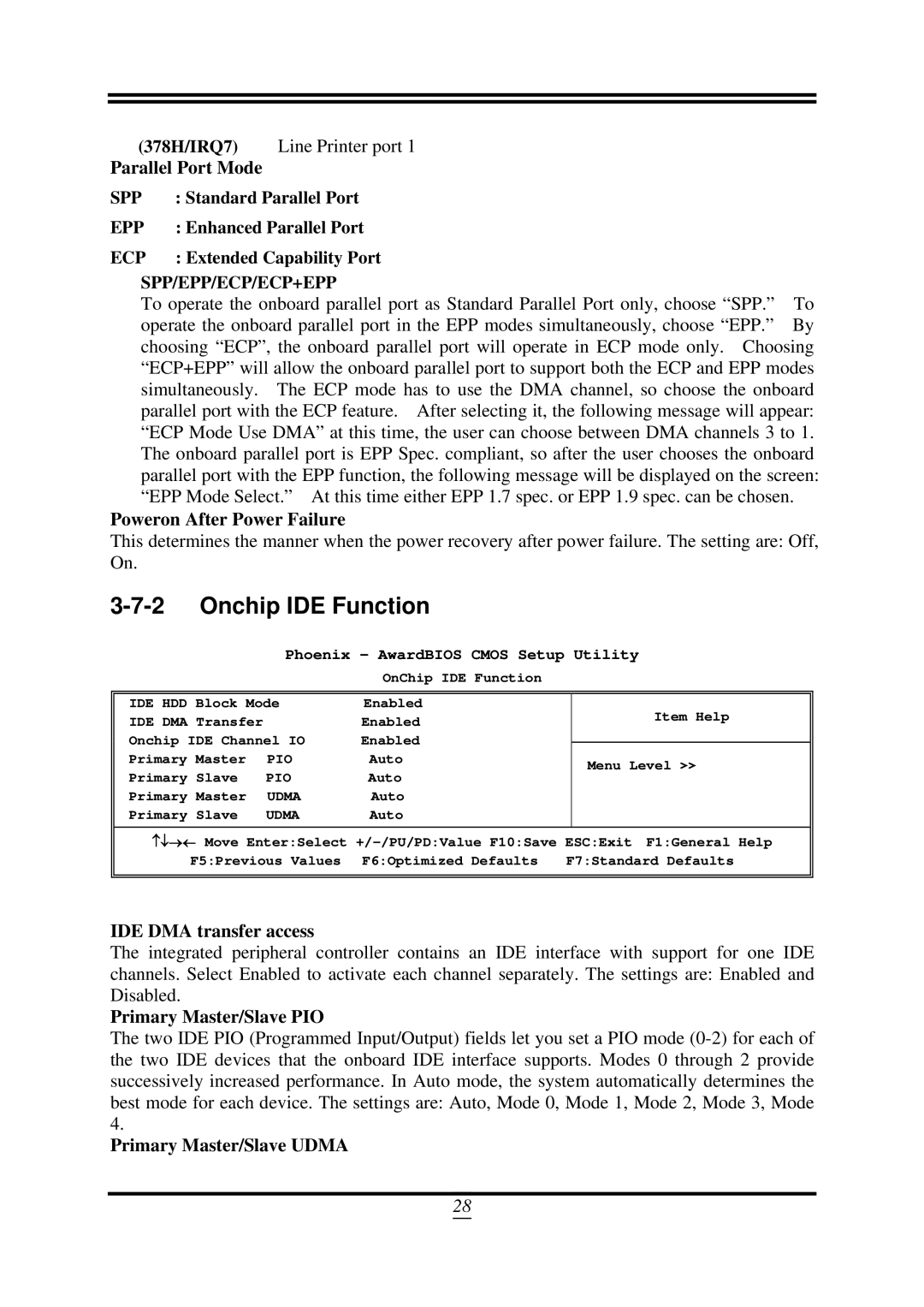
Phoenix – AwardBIOS CMOS Setup Utility
OnChip IDE Function
IDE HDD Block Mode | Enabled | Item Help | |
IDE DMA Transfer |
| Enabled | |
Onchip IDE Channel IO | Enabled |
| |
| |||
Primary Master | PIO | Auto | Menu Level >> |
Primary Slave | PIO | Auto |
|
Primary Master | UDMA | Auto |
|
Primary Slave | UDMA | Auto |
|
↑↓→← Move Enter:Select
F5:Previous Values F6:Optimized Defaults | F7:Standard Defaults |
IDE DMA transfer access
The integrated peripheral controller contains an IDE interface with support for one IDE channels. Select Enabled to activate each channel separately. The settings are: Enabled and Disabled.
Primary Master/Slave PIO
The two IDE PIO (Programmed Input/Output) fields let you set a PIO mode
Primary Master/Slave UDMA
28