Main
Table of Content
Page
Installing the motherboard to the chassis
Chapter 1 Introduction
Features Summary
Page
Introduction- 7 -
GA-7VASFS-FS Motherboard Layout
GA-7VASFS-FS
FS
Block Diagram
Page
Chapter 2 Hardware Installation Process
Step 1: Install the Central Processing Unit (CPU)
Step1-1: CPU Speed Setup
Step1-2: CPU Installation
Step1-3: CPU Heat Sink Installation
Step 2: Install memory modules
Page
Step 3: Install expansion cards
Issues To Beware Of When Installing CNR
Step 4: Connect ribbon cables, cabinet wires, and power supply
Step 4-1: I/O Back Panel Introduction
X PS/2 Keyboard and PS/2 Mouse Connector
YIEEE 1394 and USB Connector This connector supports IEEE 1394 and USB
ZParallel Port, Serial Port and SPDIF Port (LPT/COMA/SPDIF)
[USB & LAN Connector Before you connect your device(s) into USB
\Audio Connectors
Step 4-2: Connectors & Jumper Setting Introduction
- 20 -GA-7VASFS-FS Motherboard
1) ATX_12V (+12V Power Connector)
2) ATX (ATX Power)
3) CPU_FAN (CPU FAN Connector)
4) SYS_FAN (System FAN Connector)
5) PWR_FAN (Power Fan Connector)
6) IDE1/ IDE2 (IDE1/IDE2 Connector)
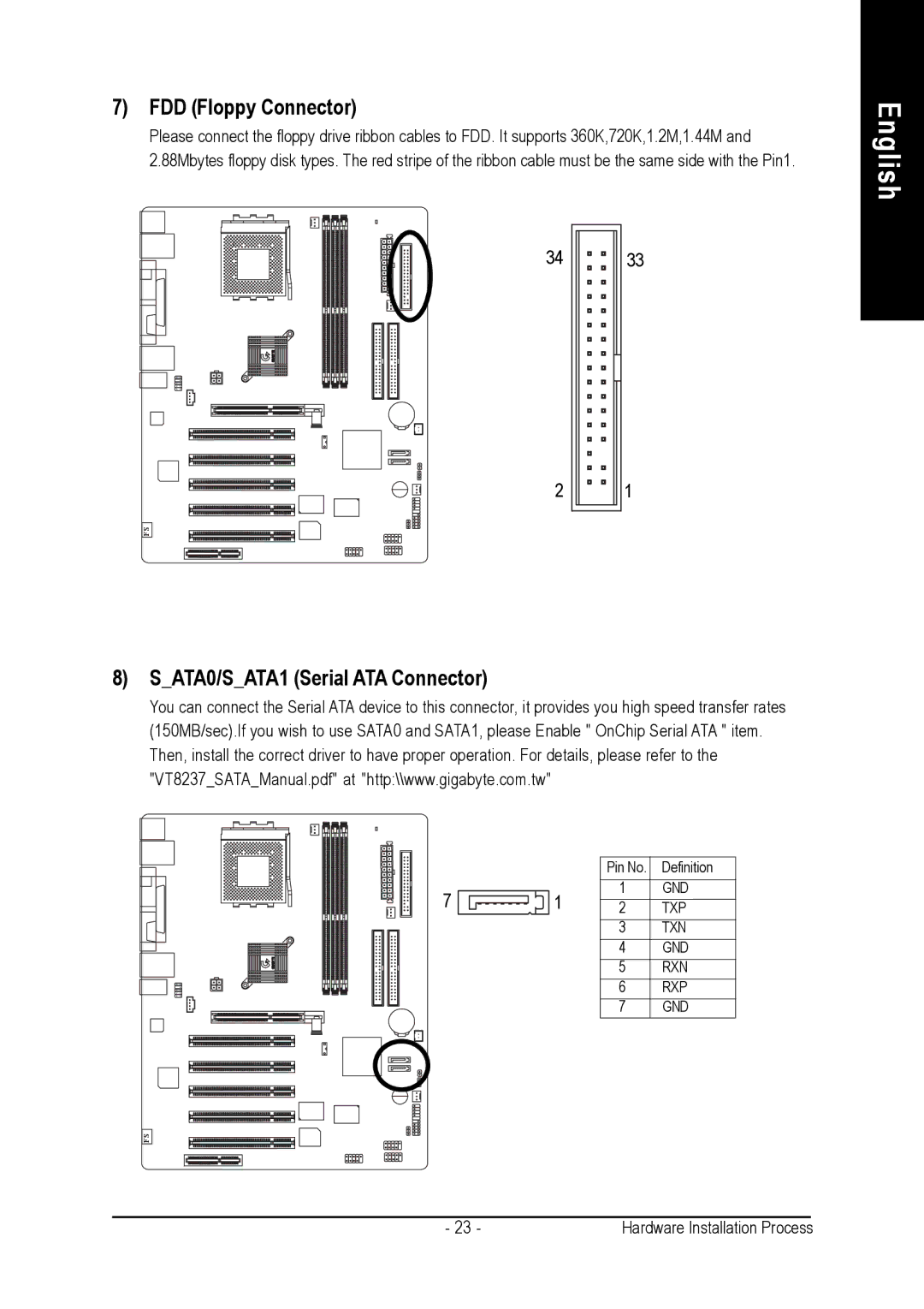
7) FDD (Floppy Connector)
8) S_ATA0/S_ATA1 (Serial ATA Connector)
9) RAM_LED
-
+
10) PWR_LED
- 25 - Hardware Installation Process
11) F_PANEL (2x10 pins connector)
12) BAT (Battery)
CAUTION
+
13) F_AUDIO (F_AUDIO Connector)
10 9
14) AUX_IN (AUX In Connector)
15) F_ USB1 / F_USB2 (Front USB Connector, Yellow)
Be careful with the polarity of the front USB connector. Check the pin assignment while you
210 19
- 28 -GA-7VASFS-FS Motherboard
17) S_IRQ (Serial IRQ Connector)
This connector is for special design, for example: PCMCIA add on card.
16) F_1394 (IEEE 1394 Connector)
18) CI (CASE OPEN)
19) CLR_CMOS (Clear CMOS jumper)
Page
Chapter 3 BIOS Setup
ENTERING
CONTROL
SETUP KEYS
The Main Menu
Page
Standard CMOS Features
Date
The date format is <week>, <month>, <day>, <year>.
Time
IDE Primary Master, Slave / IDE Secondary Master, Slave
Acoustic Management
Drive A / Drive B
Floppy 3 Mode Support (for Japan Area)
Halt on
The category determines whether the computer will stop if an error is detected during power up.
Memory
The category is display-only which is determined by POST (Power On Self Test) of the BIOS.
Advanced BIOS Features
Base Memory
Extended Memory
Password Check
System The system will not boot and will not access to Setup page if the correct
Full Screen LOGO Show
First / Second / Third Boot Device
Integrated Peripherals
OnChip IDE Channel0
OnChip IDE Channel1
Page
Page
Power Management Setup
ACPI Suspend Type
USB Device Wake-up From S3
When set at Enabled, it allows USB Device to activate the system from ACPI S3 power saving mode.
Soft-Off by PWRBTN
Page
PnP/PCI Configurations
PNP OS Installed
PCI 1/PCI 5 IRQ Assignment
PCI 2 IRQ Assignment
PCI 3 IRQ Assignment
PC Health Status
Current Voltage (V) Vcore / +3.3V / +5V / +12V /5VSB
Current System/CPU Temperature
Current CPU/SYSTEM/POWER FAN Speed (RPM)
Frequency/Voltage Control
DRAM Clock (MHz)
Load Fail-Safe Defaults
Load Fail-Safe Defaults? (Y/N)?Y
Load Fail-Safe Defaults
Load Optimized Defaults
Load Optimized Defaults? (Y/N)?Y
Load Optimized Defaults
Set Supervisor/User Password
Enter Password:
Save & Exit Setup
Save to CMOS and EXIT (Y/N)? Y
Exit Without Saving
Quit Without Saving (Y/N)? N