The AMD limit switch consists of a NAMUR slot type inductive sensor, that is actuated by a vane. Given that there is no physical contact in the operation, the limit switch has no influence on the indicator needle movement. A NAMUR amplifier with a relay output can be supplied as an optional element.
OPERATION
The indicator needle moves together with the vane mounted on its shaft. When the vane enters into the slot of the detector, the limit switch changes its state.
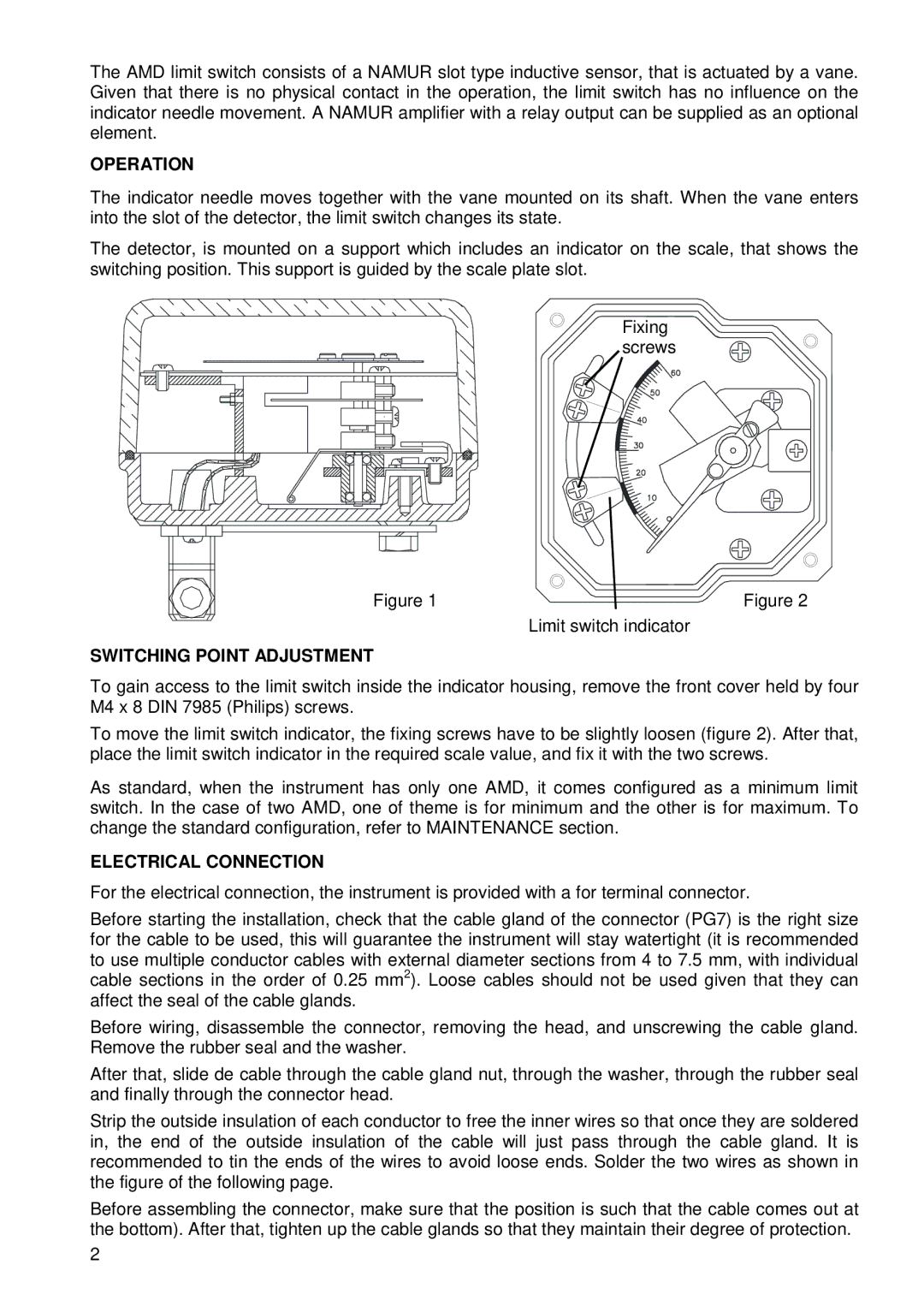
The detector, is mounted on a support which includes an indicator on the scale, that shows the switching position. This support is guided by the scale plate slot.
Fixing screws
Figure 1 | Figure 2 |
Limit switch indicator
SWITCHING POINT ADJUSTMENT
To gain access to the limit switch inside the indicator housing, remove the front cover held by four M4 x 8 DIN 7985 (Philips) screws.
To move the limit switch indicator, the fixing screws have to be slightly loosen (figure 2). After that, place the limit switch indicator in the required scale value, and fix it with the two screws.
As standard, when the instrument has only one AMD, it comes configured as a minimum limit switch. In the case of two AMD, one of theme is for minimum and the other is for maximum. To change the standard configuration, refer to MAINTENANCE section.
ELECTRICAL CONNECTION
For the electrical connection, the instrument is provided with a for terminal connector.
Before starting the installation, check that the cable gland of the connector (PG7) is the right size for the cable to be used, this will guarantee the instrument will stay watertight (it is recommended to use multiple conductor cables with external diameter sections from 4 to 7.5 mm, with individual cable sections in the order of 0.25 mm2). Loose cables should not be used given that they can affect the seal of the cable glands.
Before wiring, disassemble the connector, removing the head, and unscrewing the cable gland. Remove the rubber seal and the washer.
After that, slide de cable through the cable gland nut, through the washer, through the rubber seal and finally through the connector head.
Strip the outside insulation of each conductor to free the inner wires so that once they are soldered in, the end of the outside insulation of the cable will just pass through the cable gland. It is recommended to tin the ends of the wires to avoid loose ends. Solder the two wires as shown in the figure of the following page.
Before assembling the connector, make sure that the position is such that the cable comes out at the bottom). After that, tighten up the cable glands so that they maintain their degree of protection.
2