DX4™ |
|
|
|
|
|
|
|
|
|
|
|
|
|
|
| Controls and Features | |||
Top Panel |
|
|
|
|
|
|
|
|
|
|
|
|
|
|
|
|
|
|
|
1 | 2 |
|
| 3 |
|
| 4 |
|
| 5 | 6 | 7 |
|
|
|
|
|
| 8 |
| M I C 1 |
|
|
|
|
|
|
|
|
|
|
|
|
|
|
|
|
|
|
|
|
|
|
|
|
|
|
|
|
|
|
|
| MASTER LEVEL |
|
|
| ||
|
|
| P HONO 1 | P HONO 2 | LI N E 3 | LI N E 5 |
|
| LEFT |
|
| RIGHT |
| ||||||
|
|
|
|
|
|
|
|
|
|
|
|
| |||||||
|
|
|
| LI N E 1 |
| LI N E 2 |
| LI N E 4 |
| LI N E 6 | +5 | 0 |
| 0 +5 |
| ||||
|
|
|
|
|
|
|
|
|
|
|
|
| |||||||
|
|
|
| ��� |
| ��� |
| ��� |
| ��� |
|
|
|
|
|
|
|
| POWER |
|
|
|
|
|
|
|
|
|
|
|
|
|
|
|
| ||||
| 0 | 1 0 | 5 | 5 | 5 | 5 | 5 | 5 | 5 | 5 | 0 | 10 | 0 |
| 10 | 0 |
| 10 0 | 10 |
| M I C 1 |
| BASS |
|
| MID LOW |
| MID HIGH | TREBLE |
| |||||||||
|
|
|
|
|
|
|
|
|
|
|
|
|
| ||||||
| VO LU M E |
|
|
|
|
|
|
|
|
|
|
|
|
|
|
|
|
|
|
|
|
|
|
|
|
|
|
|
|
|
|
|
|
|
|
|
|
| ��� |
|
|
|
|
|
|
|
|
|
|
|
|
|
|
|
|
|
|
| ������������ |
|
|
|
| C U E |
| C U E |
| C U E |
| C U E |
|
|
|
|
|
|
|
| ������ ����� |
|
|
|
|
|
|
|
|
|
|
|
|
|
|
|
| ||||
|
|
|
|
|
|
|
|
|
|
|
|
|
| 0 |
|
| 10 |
|
|
|
|
|
|
|
|
|
|
|
|
|
|
|
| MASTER |
|
|
| ||
|
|
| � � � |
|
|
|
| � � � |
|
|
|
| LEVEL |
|
|
| |||
| 0 | 10 |
|
|
|
|
|
|
|
|
|
|
|
|
| ||||
| MIC 2 |
|
| ������� ����� |
|
|
|
|
|
|
|
|
|
| |||||
|
| ��� | � |
|
|
|
| ��� | � |
|
|
|
|
|
|
|
|
| |
| VOLUME |
|
|
|
|
|
|
|
|
|
|
|
|
|
|
|
|
|
|
|
|
|
|
|
|
|
|
|
|
| 0 |
| 10 | CUE |
| PGM | 0 | 10 |
|
|
|
| ASSIGN CH |
|
|
|
| ASSIGN CH | BOOTH |
|
| CUE |
| CUE | PHONES | ||||
|
|
|
|
|
|
|
|
|
|
| LEVEL |
|
| MIXING |
| LEVEL |
| ||
| 9 |
| 10 | 11 |
|
| 12 |
|
|
| 13 |
|
|
| 14 |
| 15 | 16 | |
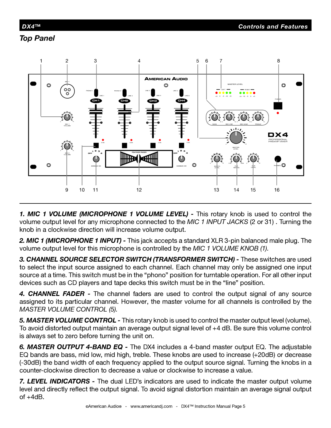
1.MIC 1 VOLUME (MICROPHONE 1 VOLUME LEVEL) - This rotary knob is used to control the volume output level for any microphone connected to the MIC 1 INPUT JACKS (2 or 31) . Turning the knob in a clockwise direction will increase volume output.
2.MIC 1 (MICROPHONE 1 INPUT) - This jack accepts a standard XLR
3.CHANNEL SOURCE SELECTOR SWITCH (TRANSFORMER SWITCH) - These switches are used to select the input source assigned to each channel. Each channel may only be assigned one input source at a time. This switch must be in the “phono” position for turntable operation. For all other input devices such as CD players and tape decks this switch must be in the “line” position.
4. CHANNEL FADER - The channel faders are used to control the output signal of any source assigned to its particular channel. However, the master volume for all channels is controlled by the
MASTER VOLUME CONTROL (5).
5.MASTER VOLUME CONTROL - This rotary knob is used to control the master output level (volume). To avoid distorted output maintain an average output signal level of +4 dB. Be sure this volume control is always set to zero before turning the unit on.
6.MASTER OUTPUT
7.LEVEL INDICATORS - The dual LED’s indicators are used to indicate the master output volume level and directly refl ect the output signal. To avoid signal distortion maintain an average signal output of +4dB.
©American Audio® - www.americandj.com - DX4™ Instruction Manual Page 5
