Start Up
Start the UPS
1.Press the ![]() button on the front panel to start the UPS.
button on the front panel to start the UPS.
–The battery charges to 90% capacity during the first four hours of normal operation. Do not expect full battery run capability during this initial charge period.
–Refer to the APC Web site, www.apc.com for battery runtimes.
2.For optimal computer system security, install PowerChute
Communication Ports
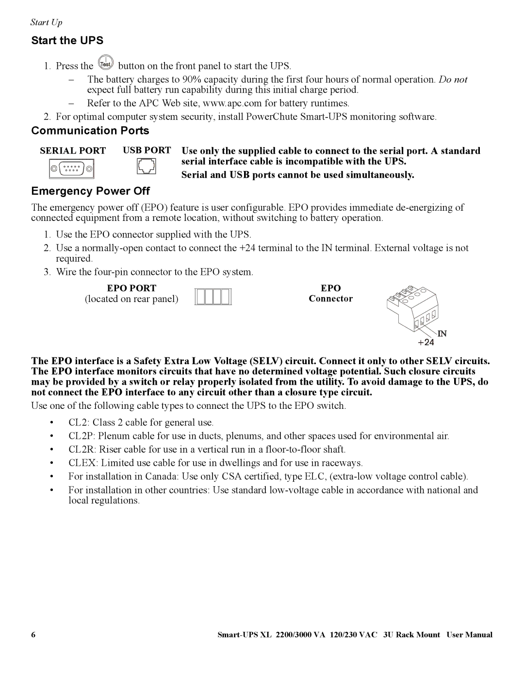
SERIAL PORT USB PORT Use only the supplied cable to connect to the serial port. A standard
serial interface cable is incompatible with the UPS. Serial and USB ports cannot be used simultaneously.
Emergency Power Off
The emergency power off (EPO) feature is user configurable. EPO provides immediate
1.Use the EPO connector supplied with the UPS.
2.Use a
3.Wire the
EPO PORT
(located on rear panel)
EPO
Connector
The EPO interface is a Safety Extra Low Voltage (SELV) circuit. Connect it only to other SELV circuits. The EPO interface monitors circuits that have no determined voltage potential. Such closure circuits may be provided by a switch or relay properly isolated from the utility. To avoid damage to the UPS, do not connect the EPO interface to any circuit other than a closure type circuit.
Use one of the following cable types to connect the UPS to the EPO switch.
•CL2: Class 2 cable for general use.
•CL2P: Plenum cable for use in ducts, plenums, and other spaces used for environmental air.
•CL2R: Riser cable for use in a vertical run in a
•CLEX: Limited use cable for use in dwellings and for use in raceways.
•For installation in Canada: Use only CSA certified, type ELC,
•For installation in other countries: Use standard
6 |
