5.0 Operation
5.2.2 Output Power bar graph
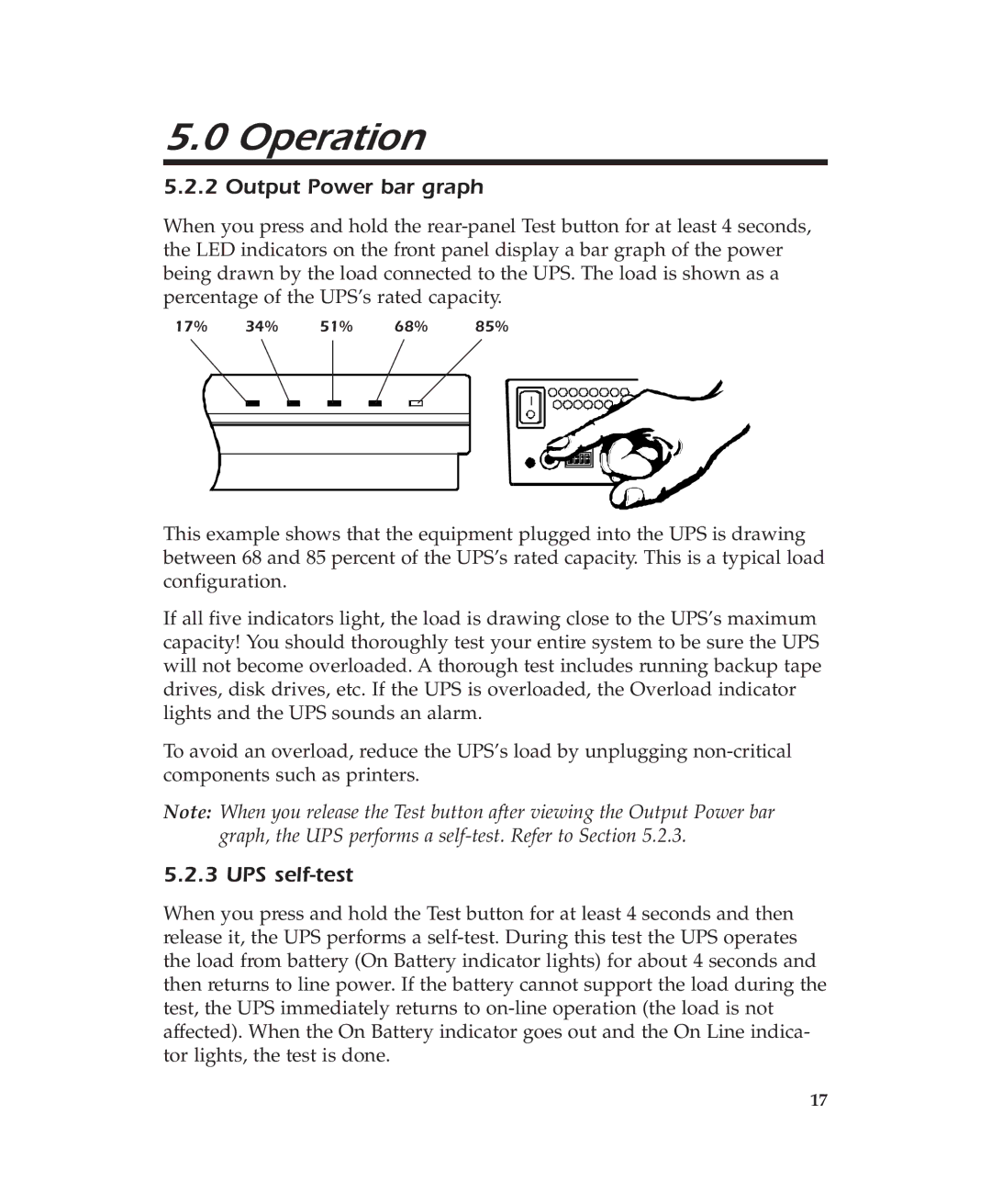
When you press and hold the
17% | 34% | 51% | 68% |
| 85% | |||||||||
|
|
|
|
|
|
|
|
|
|
|
|
|
|
|
|
|
|
|
|
|
|
|
|
|
|
|
|
|
|
|
|
|
|
|
|
|
|
|
|
|
|
|
|
|
|
|
|
|
|
|
|
|
|
|
|
|
|
|
|
|
|
|
|
|
|
|
|
|
|
|
|
|
|
|
|
|
|
|
|
|
|
|
|
|
|
|
|
|
|
|
|
|
|
|
|
|
|
|
|
|
|
|
|
|
|
|
|
|
|
|
|
|
|
|
|
|
|
|
|
This example shows that the equipment plugged into the UPS is drawing between 68 and 85 percent of the UPS’s rated capacity. This is a typical load configuration.
If all five indicators light, the load is drawing close to the UPS’s maximum capacity! You should thoroughly test your entire system to be sure the UPS will not become overloaded. A thorough test includes running backup tape drives, disk drives, etc. If the UPS is overloaded, the Overload indicator lights and the UPS sounds an alarm.
To avoid an overload, reduce the UPS’s load by unplugging
Note: When you release the Test button after viewing the Output Power bar graph, the UPS performs a
5.2.3 UPS self-test
When you press and hold the Test button for at least 4 seconds and then release it, the UPS performs a
17