6.0 UPS Monitoring
6.4 Computer Interface port
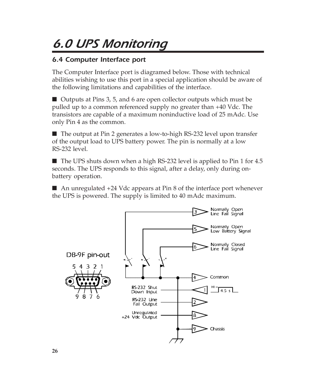
The Computer Interface port is diagramed below. Those with technical abilities wishing to use this port in a special application should be aware of the following limitations and capabilities of the interface.
■Outputs at Pins 3, 5, and 6 are open collector outputs which must be pulled up to a common referenced supply no greater than +40 Vdc. The transistors are capable of a maximum noninductive load of 25 mAdc. Use only Pin 4 as the common.
■The output at Pin 2 generates a
■The UPS shuts down when a high
■An unregulated +24 Vdc appears at Pin 8 of the interface port whenever the UPS is powered. The supply is limited to 40 mAdc maximum.
26