STATUS INDICATORS AND ALARMS | TRANSFER VOLTAGE/SENSITIVITY ADJUSTMENT (Optional) |
There are six status indicators (lights) on the front panel of the
On Line On Battery Overload Replace TX/RX ACT/LNK Battery
|
|
|
|
|
|
|
|
|
|
|
|
|
|
|
|
|
|
|
|
|
|
|
|
|
|
|
|
|
® |
|
|
|
|
|
|
|
|
|
|
|
|
|
|
|
|
|
|
|
|
|
|
| |||||
|
|
|
|
|
|
|
|
|
|
|
|
|
|
|
|
|
|
|
|
|
|
| ||||||
|
|
|
|
|
|
|
|
|
|
|
|
|
|
|
|
|
|
|
|
|
|
| ||||||
|
|
|
|
|
|
|
|
|
|
|
|
|
|
|
|
|
|
|
|
|
|
|
|
|
| |||
|
|
|
|
|
|
|
|
|
|
|
|
|
|
|
|
|
|
|
|
|
|
|
|
|
| |||
w w w.apc.com |
|
|
|
|
|
|
|
|
|
|
|
|
|
|
|
|
|
|
|
|
|
| H S 5 0 0 |
| ||||
|
|
|
|
|
|
|
|
|
|
|
|
|
|
|
|
|
|
|
|
|
|
|
|
|
|
|
|
|
|
|
|
|
|
|
|
|
|
|
|
|
|
|
|
|
|
|
|
|
|
|
|
|
|
|
|
|
|
|
|
|
|
|
|
|
|
|
|
|
|
|
|
|
|
|
|
|
|
|
|
|
|
|
|
|
|
|
|
|
|
|
|
|
|
|
|
|
|
|
|
|
|
|
|
|
|
|
|
|
|
|
|
|
|
|
|
|
|
|
|
|
|
|
|
|
|
|
|
|
|
|
|
|
|
|
|
|
|
|
|
|
|
|
|
|
On Line (green) - is illuminated whenever AC utility power is supplying power the outlets.
Overload (red) - is illuminated whenever power demand has exceeded the capacity of the
Continuous Tone - this alarm is sounded whenever the
On Battery (yellow) - is illuminated whenever the Back- UPS battery is supplying power to the equipment connected to the outlets.
Four Beeps Every 30 Seconds - this alarm is sounded whenever the
Continuous Beeping - this alarm is sounded whenever a low battery condition is reached. Battery
Replace Battery (red) - is illuminated whenever the battery is near the end of its useful life, or if the battery is not connected (see above). A battery that is near the end of its useful life has insufficient
Chirps for 1 Minute Every 5 Hours - this alarm is sounded whenever the battery has failed the automatic diagnostic test.
TX/RX (green) - is illuminated whenever the
ACT/LNK (green) - is illuminated whenever the Back- UPS is connected to equipment and is ready and waiting to send or receive data.
Circuit Breaker - the circuit breaker button located on the bottom panel of the
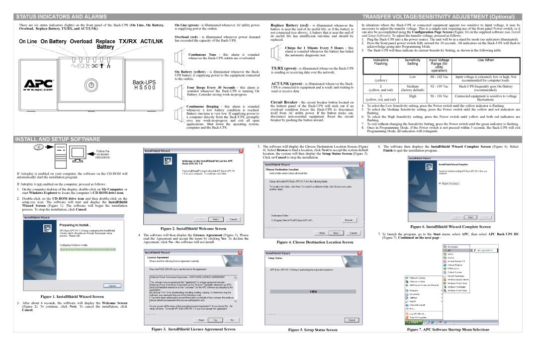
In situations where the
1.Plug the
2.Press the front panel power switch fully inward for 10 seconds. All indicators on the
3.The
Indicators | Sensitivity | Input Voltage | Use When |
Flashing | Setting | Range (for |
|
|
| utility |
|
|
| operation) |
|
1 | Low | 88 - 142 Vac | Input voltage is extremely low or high. Not |
(yellow) |
|
| recommended for computer loads. |
|
|
|
|
2 | Medium | 92 - 139 Vac | |
(yellow, and red) | (factory default) |
| (recommended). |
|
|
|
|
3 | High | 96 - 136 Vac | Connected equipment is sensitive to voltage |
(yellow, red, and red) |
|
| fluctuations. |
|
|
|
|
4.To select the Low Sensitivity setting, press the Power switch until the yellow indicator is flashing.
5.To select the Medium Sensitivity setting, press the Power switch until the yellow and red indicators are flashing.
6.To select the High Sensitivity setting, press the Power switch until yellow and both red indicators are flashing.
7.To exit without changing the Sensitivity Setting, press the Power switch until the green indicator is flashing.
8.Once in Programming Mode, if the Power switch is not pressed within 5 seconds, the
INSTALL AND SETUP SOFTWARE
Follow the ![]()
If Autoplay is enabled on your computer, the software on the
If Autoplay is not enabled on the computer, proceed as follows:
1.On the computer desktop of the display,
2.
5. The software will display the Choose Destination Location Screen (Figure | 6. The software then displays the InstallShield Wizard Complete Screen (Figure 6). Select | ||
4). Select Browse to find a location, click Next to accept the system default | Finish to quit the installation program.. | ||
location, the system will then display the Setup Status Screen (Figure 5). |
|
|
|
Click on Cancel to stop the installation. |
|
|
|
|
|
|
|
Figure 2. InstallShield Welcome Screen |
| Figure 6. InstallShield Wizard Complete Screen | ||||
|
|
|
|
|
| |
4. The software will then display the Licence Agreement (Figure 3). Please | 7. To launch the program, go to the Start menu, select APC, then select APC | |||||
read the Agreement and accept the terms by clicking Yes. To decline the | (Figure 7). Continued on the next page - | |||||
Agreement, click No - the software will not install. | Figure 4. Choose Destination Location Screen | |||||
|
|
|
|
|
|
|
|
|
|
|
|
|
|
Figure 1. InstallShield Wizard Screen
3.After about 4 seconds, the software will display the Welcome Screen (Figure 2). To continue, click Next. To cancel the installation, click Cancel.
Figure 3. InstallShield Licence Agreement Screen | Figure 5. Setup Status Screen | Figure 7. APC Software Startup Menu Selections |